Yaskawa D1000 Series Power Regenerative Converter User Manual
Page 98
4.5 Operation with the Drive Connected
98
YASKAWA ELECTRIC TOEP C710656 07C YASKAWA Power Regenerative Converter - D1000 Instruction Manual
Not Restarting Operation for Momentary Power Loss (Stopping Operation When a Momentary Power Loss Is
Detected)
Connect the “During MC on” signal from the converter to a multi-function contact input terminal on the drive that is
assigned to an external fault.
Use an N.C. input for the external fault input on the drive and set the drive to detect external faults only during operation
to prevent an external fault from being detected when the power supply is turned on.
Restarting the System for Momentary Power Losses
• A1000
Connect the “During MC on” signal from the converter to a multi-function contact input terminal on the drive that is
assigned to a Baseblock Command (N.C.).
• Control Devices Other Than the A1000
Connect the “During MC on” signal from the converter to a multi-function contact input terminal on the drive that is
assigned to External Search Command 2.
(Contact your Yaskawa representative if you are using Yaskawa drive that does not have External Search Command 2.)
■
Stopping the Converter for Faults in Peripheral Devices
If an external device fails or a fault occurs, the fault contact output on the converter is activated to stop operation.
To use an external fault, set H1- (terminal S1 to S8 function selection) to one of the values from
When an external fault is input, EF is displayed on the digital operator.
The in EF is the number of the terminal where the external fault signal was input.
Example: If an external fault signal is input to the S3 terminal, EF3 is displayed.
Select the number to set for H1- according to the combination of the following three conditions:
• Use an input contact for a signal from the peripheral device.
• Use detection of an external fault.
• Stop operation (as the operation selection when an external fault is detected).
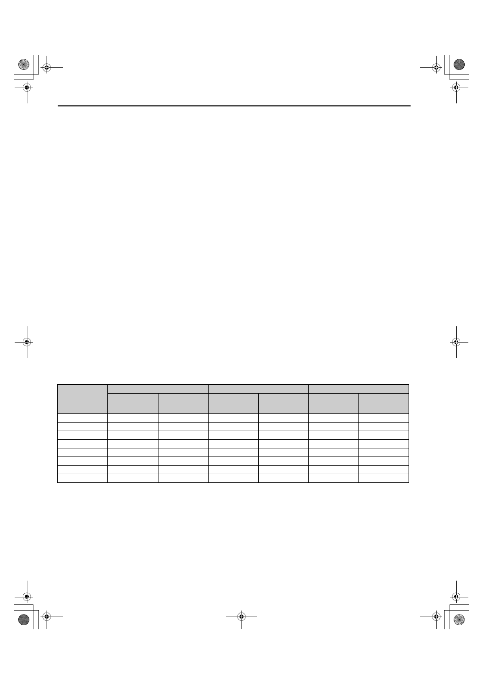
shows the relationship between the combination of conditions and the set value of H1-.
Table 4.5 Combination of Conditions
Setting Value
Input contact
Detection
Operation selection
N.O. contact
N.C. contact
Always detect
Detect only
during operation
Stop converter
(fault)
Continue
operation
(minor fault)
24
<1> When using an input contact, set whether to detect a fault when the signal opens or closes. (N.O.: External fault when closed, N.C.: External
fault when open)
<2> When using detection of a fault, set whether to always detect faults or to detect them only during operation.
–
–
–
25
–
–
–
26
–
–
–
27
–
–
–
2C
–
–
–
2D
–
–
–
2E
–
–
–
2F
–
–
–
TOEP_C710656_07C_2_0.book 98 ページ 2015年1月9日 金曜日 午後6時23分