Installing standard configuration devices, Low voltage wiring for control circuit terminals, Converter short-circuit rating – Yaskawa D1000 Series Power Regenerative Converter User Manual
Page 254
D.3 UL Standards
254
YASKAWA ELECTRIC TOEP C710656 07C YASKAWA Power Regenerative Converter - D1000 Instruction Manual
Note: Use crimp insulated terminals or insulated shrink tubing for wiring connections. Wires should have a continuous maximum
allowable temperature of 75
°C 600 Vac UL-approved vinyl-sheathed insulation.
◆ Installing Standard Configuration Devices
NOTICE: If a fuse is open or a Ground Fault Circuit Interrupter (GFCI) is tripped, check the wiring and the selection of the peripheral
devices. Check the wiring and the selection of peripheral devices to identify the cause. Contact Yaskawa before restarting the converter
or the peripheral devices if the cause cannot be identified.
Refer to
Standard Configuration Devices on page 236
for details on the standard configuration devices.
■
Low Voltage Wiring for Control Circuit Terminals
Wire low voltage wires with NEC Class 1 circuit conductors. Refer to national state or local codes for wiring. The
external power supply shall be a CSA certified or cUL Listed Class 2 power source only or equivalent.
Table D.8 Control Circuit Terminal Power Supply
■
Converter Short-Circuit Rating
This converter is suitable for use on a circuit capable of delivering not more than 100,000 RMS symmetrical amperes, 240
Vac for 200 V class converters and 480 Vac for 400 V class converters, when protected by fuses as specified on the
4A0630
4/0
× 8P
M12
100-L12
YF-1,
YET-300-1
TD-324,
TD-312
TP-100
100-051-559
250
× 8P
150-L12
YF-1,
YET-300-1
TD-325,
TD-313
TP-150
100-051-562
300
× 8P
150-L12
YF-1,
YET-300-1
TD-325,
TD-313
TP-150
100-051-562
<1> Codes refer to a set of three crimp terminals and three insulation caps. Prepare input and output wiring using two sets for each connection.
Example 1: Model 4A0130 with 300 kcmil for both input and output require one set for input terminals and one set for output terminals, so the
user should order two sets of [100-051-272].
Example 2: Model 4A0185 with 300 kcmil
× 2P for both input and output require two sets for input terminals and two sets for output terminals,
so the user should order four sets of [100-051-562].
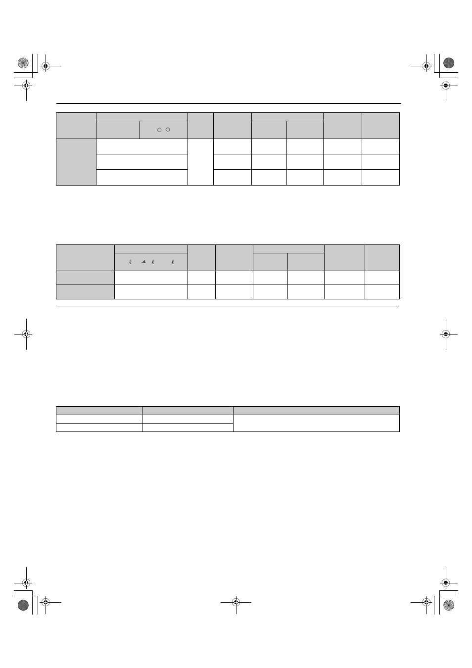
Model
Wire Gauge (AWG, kcmil)
Screw
Size
Crimp
Terminal
Model
Number
Tool
Insulation
Cap
Model No.
Code
r1/ 11, 1/ 21,
t1/ 31
Machine
No.
Die Jaw
2A0005 to 2A0020,
4A0005 to 4A0020
14
M3.5
R2-3.5
YA-4
AD-900
TP-003
100-106-516
2A0030 to 2A0130,
4A0030 to 4A0630
14
M4
R2-4
YA-4
AD-900
TP-003
100-106-517
Input / Output
Terminal Signal
Power Supply Specifications
Multi-function digital inputs
S1, S2, S3, S4, S5, S6, S7, S8, SC
Use the internal LVLC power supply of the converter. Use class 2 for
external power supply.
Multi function analog inputs
+V, -V, A1, A2, A3, AC
Model
Wire Gauge (AWG, kcmil)
Screw
Size
Crimp
Terminal
Model
Number
Tool
Insulation
Cap
Model No.
Code
<1>
R/L1S/L2T/L3
,
Machine
No.
Die Jaw
–
+
TOEP_C710656_07C_2_0.book 254 ページ 2015年1月9日 金曜日 午後6時23分