Yaskawa D1000 Series Power Regenerative Converter User Manual
Page 189
B.2 Parameter Tables
YASKAWA ELECTRIC TOEP C710656 07C YASKAWA Power Regenerative Converter - D1000 Instruction Manual
189
B
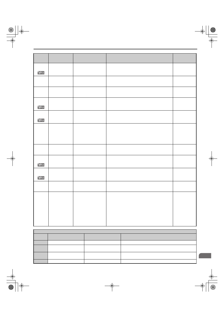
H3-04
(412H)
Terminal A1 Bias
Setting
Terminal A1 Bias
Sets the level of the input value selected in H3-02 when 0
V is input at terminal A1.
Default: 0.0%
Min.: -999.9%
Max.: 999.9%
H3-05
(413H)
Terminal A3 Signal
Level Selection
Term A3 Signal
0: 0-10V (LowLim=0)
1: 0-10V (BipolRef)
0: 0 to 10 V
1: -10 to 10 V
Default: 0
Min.: 0
Max.: 1
H3-06
(414H)
Terminal A3
Function Selection
Terminal A3 Sel
Sets the function of terminal A3.
Default: F
Min.: F
Max.: 19
H3-07
(415H)
Terminal A3 Gain
Setting
Terminal A3 Gain
Sets the level of the input value selected in H3-06 when 10
V is input at terminal A3.
Default: 100.0%
Min.: -999.9%
Max.: 999.9%
H3-08
(416H)
Terminal A3 Bias
Setting
Terminal A3 Bias
Sets the level of the input value selected in H3-06 when 0
V is input at terminal A3.
Default: 0.0%
Min.: -999.9%
Max.: 999.9%
H3-09
(417H)
Terminal A2 Signal
Level Selection
Term A2 Level
0: 0-10V, (LowLim=0)
1: 0-10V, (BipolRef)
2: 4-20 mA
3: 0-20 mA
0: 0 to 10 V
1: -10 to 10 V
2: 4 to 20 mA
3: 0 to 20 mA
Note: Use DIP switch S1 to set input terminal A2 for a
current or a voltage input signal.
Default: 2
Min.: 0
Max.: 3
H3-10
(418H)
Terminal A2
Function Selection
Term A2 FuncSel
Sets the function of terminal A2.
Default: F
Min.: F
Max.: 19
H3-11
(419H)
Terminal A2 Gain
Setting
Terminal A2 Gain
Sets the level of the input value selected in H3-10 when 10
V (20 mA) is input at terminal A2.
Default: 100.0%
Min.: -999.9%
Max.: 999.9%
H3-12
(41AH)
Terminal A2 Bias
Setting
Terminal A2 Bias
Sets the level of the input value selected in H3-10 when 0
V (0 or 4 mA) is input at terminal A2.
Default: 0.0%
Min.: -999.9%
Max.: 999.9%
H3-13
(41BH)
Analog Input Filter
Time Constant
A1/A2 Filter T
Sets a primary delay filter time constant for terminals A1,
A2, and A3. Used for electrical noise filtering.
Default: 0.03 s
Min.: 0.00 s
Max.: 2.00 s
H3-14
(41CH)
Analog Input
Terminal Enable
Selection
A1/A2 Sel
1: A1 Available
2: A2 Available
3: A1/A2 Available
4: A3 Available
5: A1/A3 Available
6: A2/A3 Available
7: All Available
Determines which analog input terminals will be enabled
when a digital input programmed for “Analog input
enable” (H1- = C) is activated.
1: Terminal A1 only
2: Terminal A2 only
3: Terminals A1 and A2 only
4: Terminal A3 only
5: Terminals A1 and A3
6: Terminals A2 and A3
7: All terminals enabled
Default: 7
Min.: 1
Max.: 7
H3 Analog Output Settings
H3-
Setting
Function
LCD Display
Description
F
Through mode
Through mode
Set this value when using the terminal in the pass-through mode.
10
Power Supply Side Active
Current Limit
Motoring I Limit
10 V = Converter rated current
12
Regeneration side Active
Current Limit
Regen I limit
10 V = Converter rated current
19
Voltage Reference
DC V Reference
10 V = Maximum value in d8-01
No.
(Address
Hex)
Name
LCD Display
Description
Values
TOEP_C710656_07C_2_0.book 189 ページ 2015年1月9日 金曜日 午後6時23分