U: monitors, U1 - 10, U1 - 11 – Yaskawa D1000 Series Power Regenerative Converter User Manual
Page 195: U1 - 12
B.2 Parameter Tables
YASKAWA ELECTRIC TOEP C710656 07C YASKAWA Power Regenerative Converter - D1000 Instruction Manual
195
B
◆ U: Monitors
Monitor parameters allow the user to view converter status, fault information, and other data concerning converter
operation.
o4-19
(113AH)
Power Unit Price
Cost per 1 kWh
This parameter is used to calculate the power rate that is
displayed for User Monitors U9-07 through U9-14.
Set the price per 1 kWh.
Default: 000.00
Min.: 000.00
Max.: 650.00
<7> Parameter is available in software versions PRG: 2003 and later (PRG: 3010 and later in 4A0630).
No.
(Address
Hex)
Name
LCD
Display
Description
Analog
Output
Level
Unit
U1: Operation Status Monitors
U1-10
(49H)
Input Terminal
Status
Input Term
Sts
Displays the input terminal status.
No signal
output
available
–
U1-11
(4AH)
Output Terminal
Status
Output
Term Sts
Displays the output terminal status.
No signal
output
available
–
U1-12
(4BH)
Drive Status
Int Ctl Sts 1
Verifies the converter operation status.
No signal
output
available
–
U1-13
(4EH)
Terminal A1 Input
Level
Term A1
Level
Displays the signal level to analog input terminal A1.
10 V: 100%
0.1%
No.
(Address
Hex)
Name
LCD Display
Description
Values
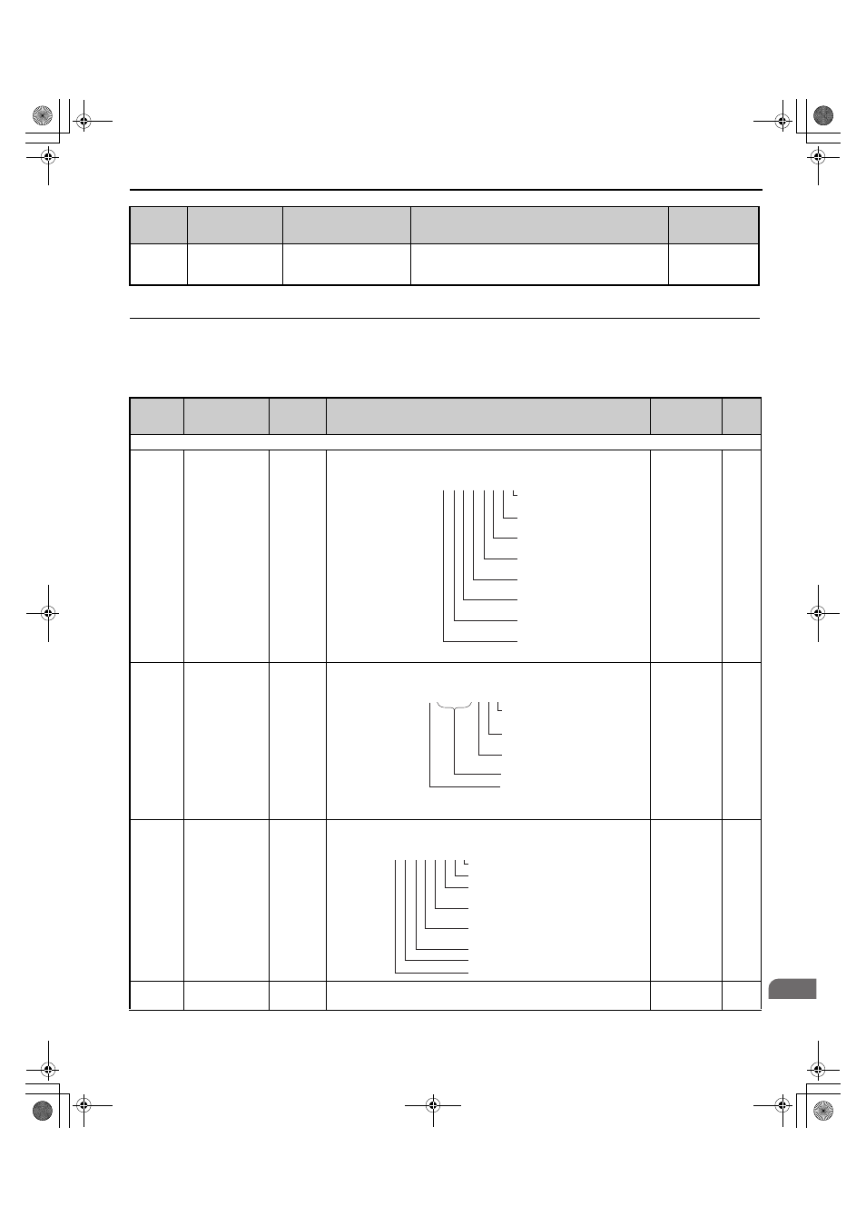
U1 - 10=
0 0 0 0 0 0 0 0
Digital input 1
(terminal S1 enabled)
Digital input 2
(terminal S2 enabled)
Digital input 3
(terminal S3 enabled)
Digital input 4
(terminal S4 enabled)
Digital input 5
(terminal S5 enabled)
Digital input 6
(terminal S6 enabled)
Digital input 7
(terminal S7 enabled)
Digital input 8
(terminal S8 enabled)
1: ON 0: OFF
U1 - 11=
0 0 0 0 0 0 0 0
Multi-Function Relay Output
(terminal M1-M2)
Multi-Function Relay Output
(terminal M3-M4)
Multi-Function Relay Output
(terminal M5-M6)
Reserved
Fault Relay
(terminal MA/MB-MC closed
MA/MB-MC open)
1: ON 0: OFF
YAI
U1 - 12=
0 0 0 0 0 0 0 0
Bit 0: AUv reset. (0: Not completed, 1: Reset)
Bit 1: PF3 reset (0: Not completed, 1: Reset)
Bit 2: Rated frequency detection
(0: Not completed, 1: Completed)
Bit 3: Phase order detection
(0: Not completed, 1: Completed)
Bit 4: Power supply established
(0: Not completed, 1: Completed)
Bit 5: Fdv detection (0: Not detected, 1: Detected)
Bit 6: PF3 detection (0: Not detected, 1: Detected)
Bit 7: Reserved.
TOEP_C710656_07C_2_0.book 195 ページ 2015年1月9日 金曜日 午後6時23分