Terminal configuration, Wire size and torque specifications, 9 control circuit wiring – Yaskawa D1000 Series Power Regenerative Converter User Manual
Page 78
3.9 Control Circuit Wiring
78
YASKAWA ELECTRIC TOEP C710656 07C YASKAWA Power Regenerative Converter - D1000 Instruction Manual
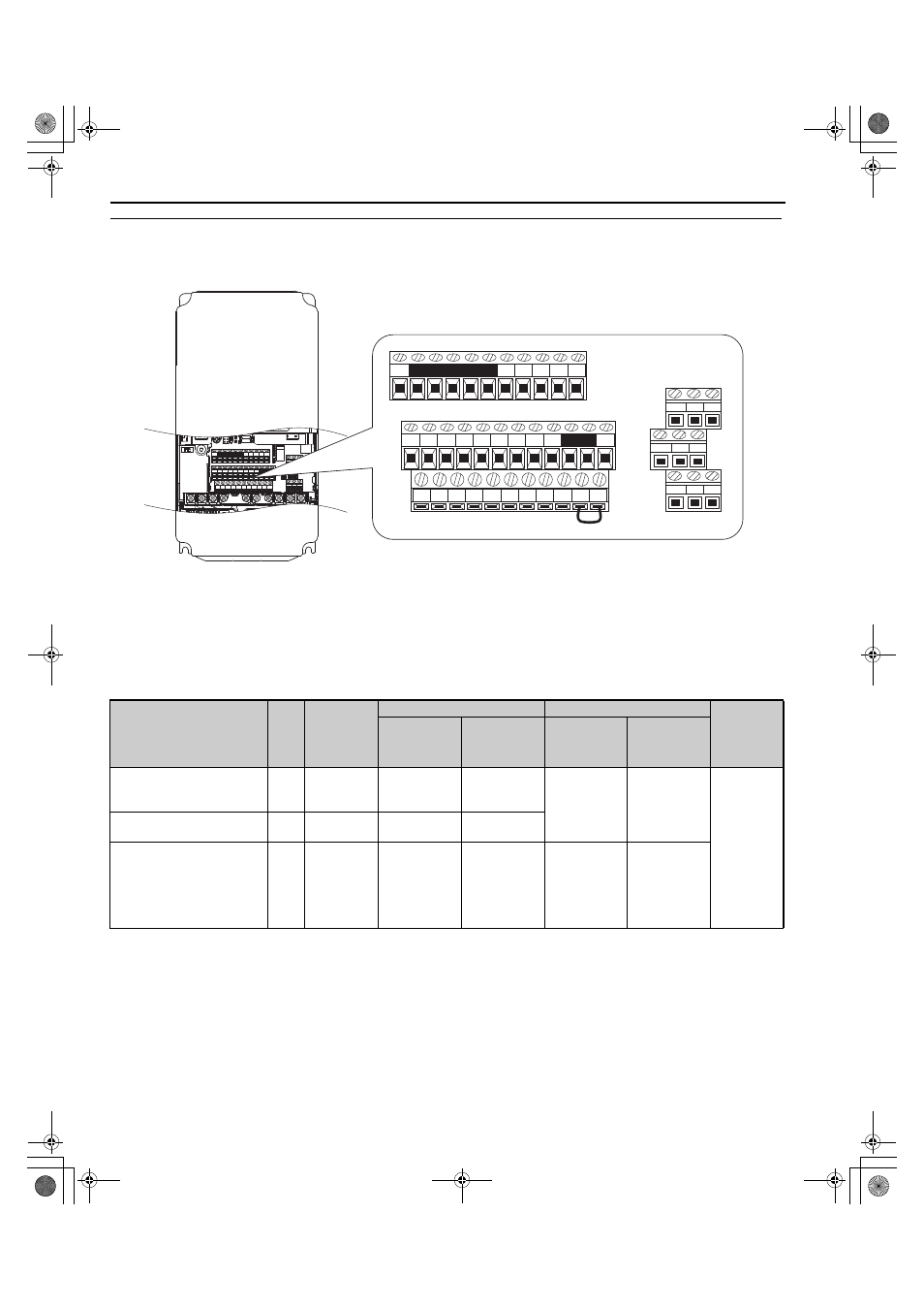
◆ Terminal Configuration
The control circuit terminals are arranged as shown in
.
Figure 3.37
Figure 3.34 Control Circuit Terminal Arrangement
■
Wire Size and Torque Specifications
Select appropriate wire type and gauges from
For simpler and more reliable wiring, use crimp ferrules on the wire ends. Refer to
for ferrule terminal types
and sizes.
Table 3.11 Wire Gauge and Torque Specifications
Terminal
Screw
Size
Tightening
Torque
Nm
(lbin.)
Bare Wire Terminal
Ferrule-Type Terminal
Wire Type
Recomm.
Gauge
mm
2
(AWG)
Applicable
Gauge
mm
2
(AWG)
Recomm.
Gauge
mm
2
(AWG)
Applicable
Gauge
mm
2
(AWG)
FM, AC, AM, SC, SP, SN, A1,
A2, A3, +V, -V, S1 to S8, MA,
MB, MC, M1 to M6
M3.5
0.8 to 1.0
(7.1 to 8.6)
0.75
(18)
0.5 to 2
(20 to 14)
–
–
Shielded wire,
etc.
E (G)
M3.5
0.8 to 1.0
(7.1 to 8.6)
1.25
(12)
0.5 to 2
(20 to 14)
IG, R+, R-, S+, S-
M2
0.22 to 0.25
(1.9 to 2.2)
0.75
(18)
Stranded wire:
0.25 to 1.0
(24 to 17)
Solid wire:
0.25 to 1.5
(24 to 16)
0.5
(20)
0.25 to 0.5
(24 to 20)
㪤㪘 㪤㪙 㪤㪚
㪤㪊 㪤㪋 㪤㪍
㪤㪈 㪤㪉 㪤㪌
㪛㪤㪄
㪠㪞 㪩㪂 㪩㪄 㪪㪂 㪪㪄
㪟㪚 㪟㪈 㪟㪉
㪛㪤㪂
㪜㩿㪞㪀
㪘㪊 㪝㪤 㪘㪤 㪘㪚 㪤㪧 㪩㪧 㪘㪚
㪘㪚 㪭㪄 㪘㪈 㪘㪉
㪭㪂
㪪㪈 㪪㪉 㪪㪊 㪪㪋 㪪㪌 㪪㪍 㪪㪎
㪪㪥 㪪㪚 㪪㪧
㪪㪏
㪤㪘 㪤㪙 㪤㪚
㪤㪊 㪤㪋 㪤㪍
㪤㪈 㪤㪉 㪤㪌
㪘㪊 㪝㪤 㪘㪤 㪘㪚 㪤㪧 㪩㪧 㪘㪚
㪘㪚 㪭㪄 㪘㪈 㪘㪉
㪭㪂
㪪㪈 㪪㪉 㪪㪊 㪪㪋 㪪㪌 㪪㪍 㪪㪎
㪪㪥 㪪㪚 㪪㪧
㪪㪏
㪛㪤㪄
㪠㪞 㪩㪂 㪩㪄 㪪㪂 㪪㪄
㪟㪚 㪟㪈 㪟㪉
㪛㪤㪂
㪜㩿㪞㪀
YAI
TOEP_C710656_07C_2_0.book 78 ページ 2015年1月9日 金曜日 午後6時23分