Emc filters, D.2 european standards, Connection diagram – Yaskawa D1000 Series Power Regenerative Converter User Manual
Page 239
D.2 European Standards
YASKAWA ELECTRIC TOEP C710656 07C YASKAWA Power Regenerative Converter - D1000 Instruction Manual
239
St
and
ar
ds Co
mpl
ia
nce
D
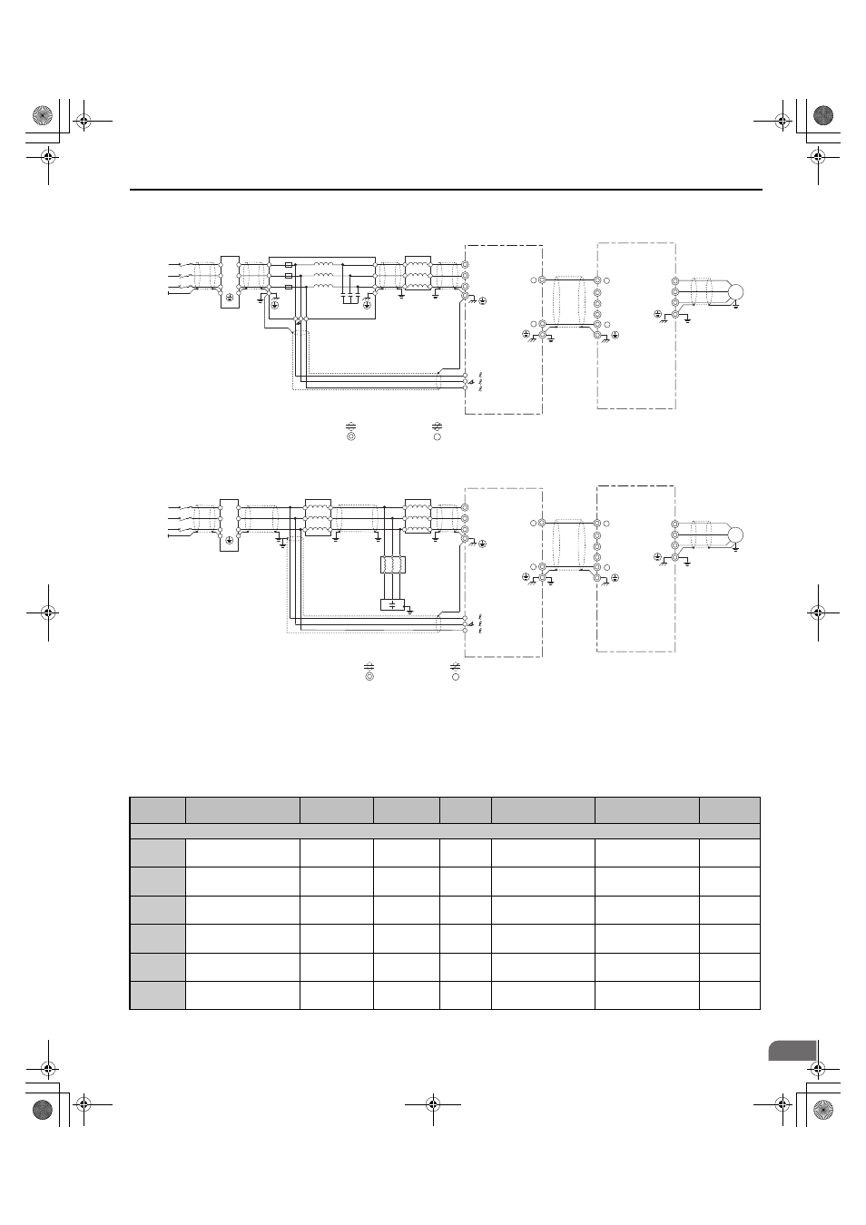
Connection Diagram
Figure D.3
Figure D.3 Wiring Diagram for EMC (Models 2A0005 to 2A0130, 4A0005 to 4A0185)
Figure D.4
Figure D.4 Wiring Diagram for EMC (Models 4A0270, 4A0370)
■
EMC Filters
The converter should be installed with the EMC filters listed in
in order to comply with the IEC/EN 61800-3
requirements.
Table D.4 IEC/EN 61800-3 Filters
Model
Type
Manufacturer
Rated
Current (A)
Weight
kg (lb)
Dimensions
[W
× H × D] mm (in)
Y
× X
mm (in)
Figure
200 V Class
2A0005
RTEN-2030C6E3-00
TDK-Lambda
30
1.1
(1.2)
170
× 54 × 90
(5.7
× 1.7 × 2.8)
80
× 160
(2.4
× 5.1)
2A0010
RTEN-2030C6E3-00
TDK-Lambda
30
1.1
(1.2)
170
× 54 × 90
(5.7
× 1.7 × 2.8)
80
× 160
(2.4
× 5.1)
2A0020
RTEN-2080G6E2-00
TDK-Lambda
80
3.9
(8.6)
267
× 85 × 161
(10.5
× 3.3 × 6.3)
135
× 247
(5.3
× 9.7)
2A0030
RTEN-2100G6E3-00
TDK-Lambda
100
5.1
(9.3)
285
× 79 × 152
(10.5
× 3.3 × 6.3)
126
× 265
(5.3
× 9.7)
2A0050
RTEN-2150G6E2-00
TDK-Lambda
150
6.5
(14.3)
290
× 88 × 190
(11.4
× 3.5 × 7.5)
164
× 270
(6.5
× 10.6)
2A0065
B84143B0320T176
EPCOS
320
20.7
(55)
605
× 140 × 220
(23.8
× 5.5 × 8.6)
200
× 450
(7.9
× 17.7)
D1000
+
-
(Ground)
Converter
Input-side AC
reactor
U
V
W
X
Y
Z
R/L1
S/L2
T/L3
GFCI
or
MCCB
Harmonic
Filter Module
X
Y
Z
t
r
R/L1
S/L2
T/L3
A1000
Drive
+
R/L1
S/L2
T/L3
-
IM
U/T1
V/T2
W/T3
Motor
Line
filter
PE
Ground
r1/ 11
1/ 21
t1/ 31
Three-
Phase
Power
Supply
shielded line
twisted-pair shielded line
main circuit terminal
control circuit terminal
YAI
D1000
+
-
U
V
W
X
Y
Z
R/L1
S/L2
T/L3
A1000
+
R/L1
S/L2
T/L3
-
IM
U/T1
V/T2
W/T3
PE
U
V
W
X
Y
Z
Reactor for
harmonic filter
U V W
U V W
X Y Z
Capacitor for
harmonic filter
E
r1/
11
1/
21
t1/
31
(Ground)
Converter
Input-side AC
reactor 1
GFCI
or
MCCB
Input-side AC
reactor 2
Drive
Motor
Line
filter
Ground
Three-
Phase
Power
Supply
shielded line
twisted-pair shielded line
main circuit terminal
control circuit terminal
YAI
TOEP_C710656_07C_2_0.book 239 ページ 2015年1月9日 金曜日 午後6時23分