Wiring diagram for multiple connections, Rs-485 interface, D1000 – Yaskawa D1000 Series Power Regenerative Converter User Manual
Page 207
Advertising
C.3 Connecting to a Network
YASKAWA ELECTRIC TOEP C710656 07C YASKAWA Power Regenerative Converter - D1000 Instruction Manual
207
MEMO
BUS/Mod
bus
Co
mmunica
tion
s
C
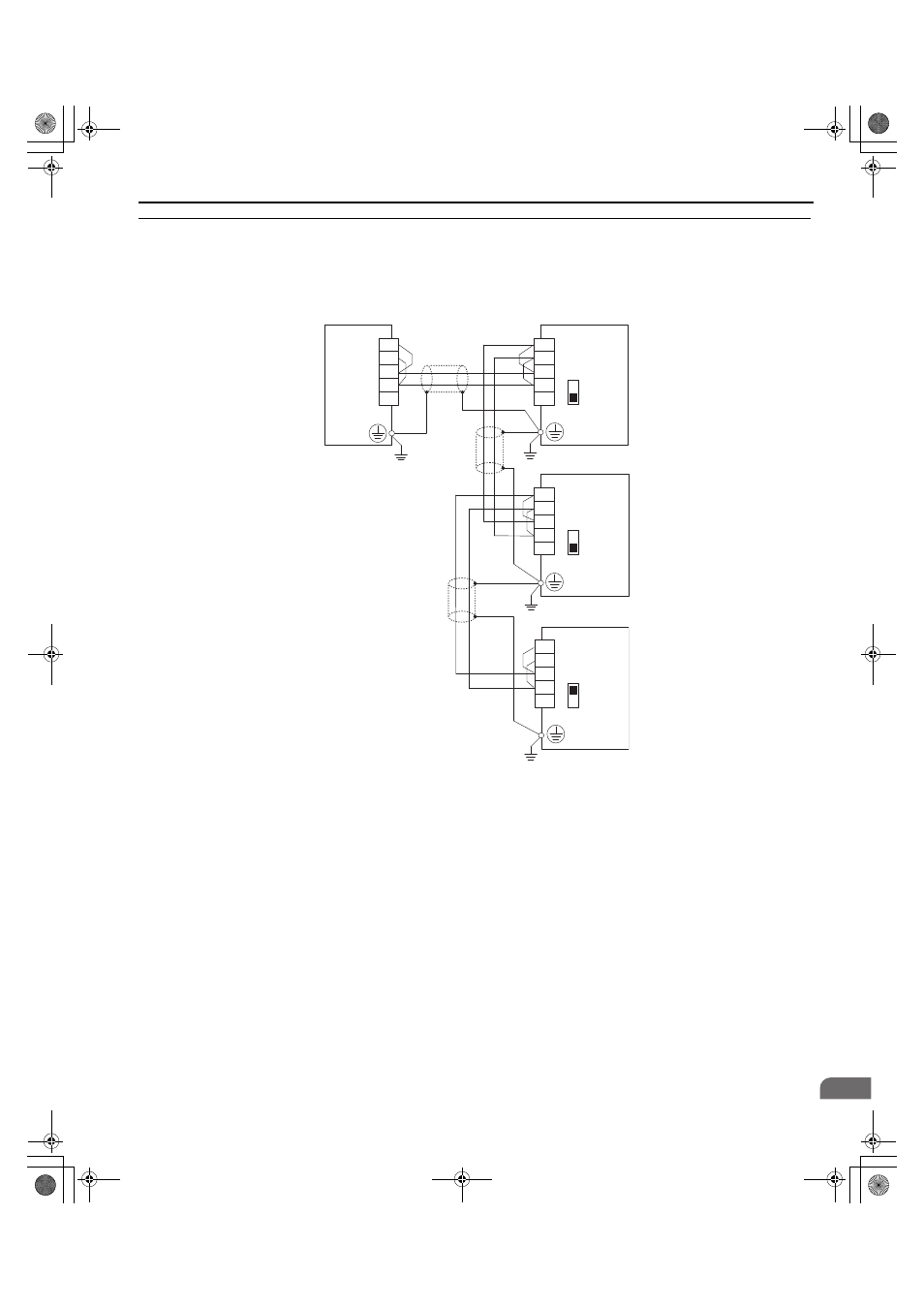
◆ Wiring Diagram for Multiple Connections
and
explain the wiring diagrams for multiple connections using MEMOBUS/Modbus
communication.
■
RS-485 Interface
Figure C.3
Figure C.3 RS-485 Interface
Note: 1. Set DIP switch S2 to the ON position on the converter located at the end of the network. Set DIP switch S2 to the OFF positions on all
other slave devices.
2. Set H5-07 to 1 when using the RS-485 interface.
Converter
S2
S2
S2
S–
S+
R–
R+
IG
S–
S+
R–
R+
IG
Converter
S–
S+
R–
R+
IG
R–
R+
S–
S+
IG
PLC
Converter
OFF
OFF
ON
D1000
TOEP_C710656_07C_2_0.book 207 ページ 2015年1月9日 金曜日 午後6時23分
Advertising