Precautions and instructions for installation, Precautions and, For det – Yaskawa D1000 Series Power Regenerative Converter User Manual
Page 32: Ording to, Figure 2.5, Set parameter, Installation screws
2.2 Mechanical Installation
32
YASKAWA ELECTRIC TOEP C710656 07C YASKAWA Power Regenerative Converter - D1000 Instruction Manual
■
Installation Screws
Refer to
Exterior and Mounting Dimensions on page 35
for the sizes of the installation screws.
◆ Precautions and Instructions for Installation
Read the following precautions and instructions before installing models 4A0270 to 4A0630.
WARNING! Crush Hazard. Observe the following instructions and precautions. Failure to comply could result in serious injury or death
from falling equipment.
• Only use vertical suspension to temporarily lift the converter during installation to an enclosure panel.
• Do not use vertical suspension to transport the converter.
• Use screws to securely affix the converter front cover, terminal blocks, and other converter components
prior to vertical suspension.
• Do not subject the converter to vibration or impact greater than 1.96 m/s
2
(0.2 G) while it is suspended by
the wires.
• Do not attempt to flip the converter over while it is suspended by the wires.
• Do not leave the converter unattended while it is suspended by the wires.
■
Horizontal Suspension of Models 2A0065 to 2A0130 and 4A0130 to 4A0370
To make a wire hanger or frame for use when lifting the converter with a crane, lay the converter in a horizontal position
and pass a wire through the holes of the four eye bolts.
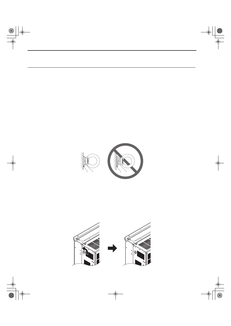
NOTICE: Damage to Equipment. When lifting the converter, confirm that the spring washer is fully closed. Failure to comply may
deform or damage the converter when lifted.
Figure 2.5
Figure 2.5 Details of Spring Washers
■
Vertical Suspension of Models 2A0065 to 2A0130 and 4A0130 to 4A0630
Models 2A0065 to 2A0130 and 4A0130 to 4A0370
When vertical suspension of the converter is required in an enclosure panel, the orientation of the eye bolts for these
converter models can be easily changed by turning the eye bolts counterclockwise 90 degrees.
Figure 2.6
Figure 2.6 Adjusting Angle of Eye Bolts
A – No space between converter
and washer
C – Space between converter and
washer
B – Spring washer: Fully closed
D – Spring washer: Open
B
A
C
D
TOEP_C710656_07C_2_0.book 32 ページ 2015年1月9日 金曜日 午後6時23分