9 setting motor overload detection level, Linear – Yaskawa Sigma-5 User Manual: Design and Maintenance - Linear Motors MECHATROLINK-III Communications Reference User Manual
Page 107
4.3 Basic Functions Settings
4-19
4
Op
er
at
io
n
4.3.9 Setting Motor Overload Detection Level
In this SERVOPACK, the detection timing of the warnings and alarms can be changed by changing how to
detect an overload warning (A.910) and overload (low load) alarm (A.720).
The overload characteristics and the detection level of the overload (high load) alarm (A.710) cannot be
changed.
(1) Changing Detection Timing of Overload Warning (A.910)
The overload warning level is set by default to 20% so that an overload warning is detected in 20% of the time
required to detect an overload alarm. The time required to detect an overload warning can be changed by
changing the setting of the overload warning level (Pn52B). This protective function enables the warning out-
put signal (/WARN) to serve as a protective function and to be output at the best timing for your system.
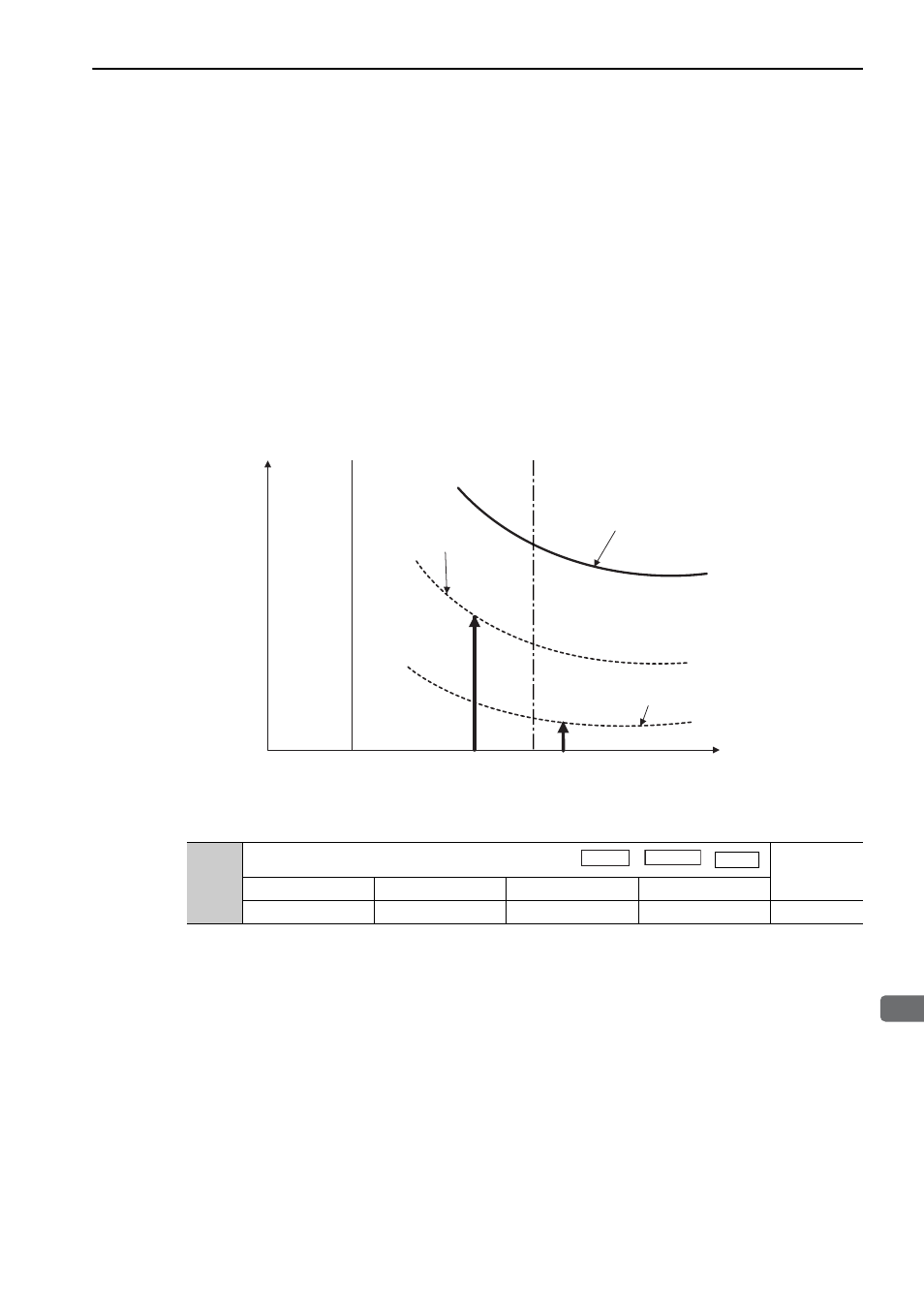
The following graph shows an example of the detection of an overload warning when the overload warning
level (Pn52B) is changed from 20% to 50%. An overload warning is detected in half of the time required to
detect an overload alarm.
Note: For details, refer to Overload Characteristics listed in the section for the relevant servomotor in the
Σ
-V Series Prod-
uct Catalog (No.: KAEP S800000 42).
Pn52B
Overload Warning Level
Classification
Setting Range
Setting Unit
Factory Setting
When Enabled
1 to 100
1%
20
Immediately
Setup
200%
100%
Overload detection time
Detection curve of
overload alarm
Detection curve of overload warning
when Pn52B=20% (factory setting)
Detection curve of
overload warning when
Pn52B=50%
Force reference [%]
Linear
Speed
Position
Force