Linear – Yaskawa Sigma-5 User Manual: Design and Maintenance - Linear Motors MECHATROLINK-III Communications Reference User Manual
Page 116
4 Operation
4.4.4 Encoder Output Pulses
4-28
(4) Precautions When Using an Incremental Linear Scale by Magnescale
When an incremental linear scale by Magnescale Co., Ltd. is used, the count direction of the linear scale deter-
mines if a phase-C pulse (CN1-21, CN1-22) is output and counted.
Note: The count direction (counting up or down) of the linear scale determines if a phase-C pulse is output. The output of
the pulse does not depend on the setting of the parameter: Pn000.0 (direction selection).
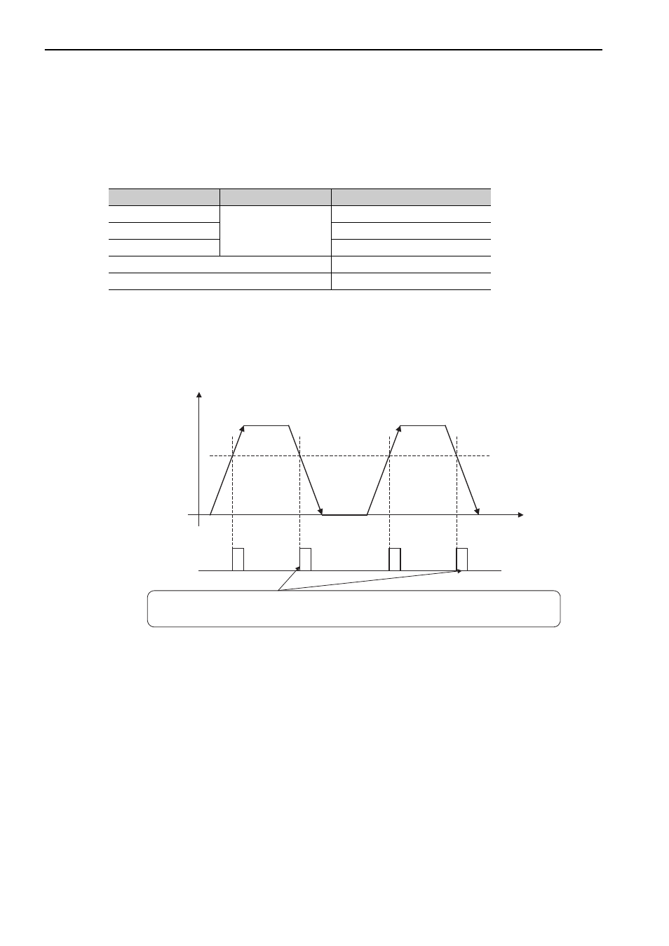
When Passing 1st
Zero Point in Forward Direction and Returning after Power ON
After the power is turned on, the phase-C pulse (CN1-21, CN1-22) is output when the linear scale moves for-
ward and its detection head first passes the phase-C detection position. After the detection head of the linear
scale passes the detection position in a forward direction, the phase-C pulse is output when the head passes the
position regardless of the direction of the linear scale’s movement.
Model
Interpolator
Scale pitch (
μm)
SL710
PL101-RY
MJ620-T13
800
SL720
800
SL730
800
SR75
80
SR85
80
Scale count-up direction
Phase-C detection position
Power ON
Time
Phase-C pulse output
The phase-C pulse is also output when the detection head of the linear scale passes
this point in reverse, because the SERVOPACK has recorded the position
where the phase-C pulse was originally output when first passing the position in the forward direction.
Linear