4 holding brakes, 1) wiring example, Mecha – Yaskawa Sigma-5 User Manual: Design and Maintenance - Linear Motors MECHATROLINK-III Communications Reference User Manual
Page 97: Linear
4.3 Basic Functions Settings
4-9
4
Op
er
at
io
n
4.3.4 Holding Brakes
A holding brake is a brake used to hold the position of the movable part of the machine when the SERVO-
PACK is turned OFF so that movable part does not move due to gravity or external forces. The brake is not
included, so if necessary, install a holding brake on the machine.
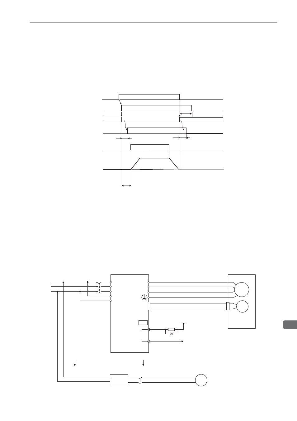
There is a delay in the braking operation. Set the following ON/OFF timing.
∗1. The operation delay time of the brake depends on the model. Check the operation delay time of the brake being used.
∗2. After the SV_ON command has been sent and 50 ms has passed since the brake was released, output the reference
from the host controller to the SERVOPACK.
∗3. Use Pn506, Pn508, and Pn583 to set the timing of when the brake will be activated and when the servomotor power
will be turned OFF.
(1) Wiring Example
Use the brake signal (/BK) and the brake power supply to form a brake ON/OFF circuit. The following dia-
gram shows a standard wiring example.
The timing can be easily set using the brake signal (/BK).
Note: A brake and its power supply are not included.
*1
*2
0
*1
*3
Servo ON command
(SV_ON)
Servomotor power
Brake signal (/BK)
Brake contact part
(lining)
Position reference/
Speed reference
Motor speed
OFF
OFF
OFF
OFF
OFF
OFF
ON
ON
ON
Brake release
Brake applied
Brake applied
MECHA
M
ENC
U
V
W
CN2
AC DC
BK-RY
BK-RY
+24 V
L1
L2
L3
L1C
L2C
(/BK+)
(/BK-)
CN1
1D
0 V
Servomotor
SERVOPACK
Power supply
Brake power
supply
DC side
AC side
BK
Linear