Yaskawa Sigma-5 User Manual: Design and Maintenance - Linear Motors MECHATROLINK-III Communications Reference User Manual
Page 277
8 Troubleshooting
8.1.2 Troubleshooting of Alarms
8-16
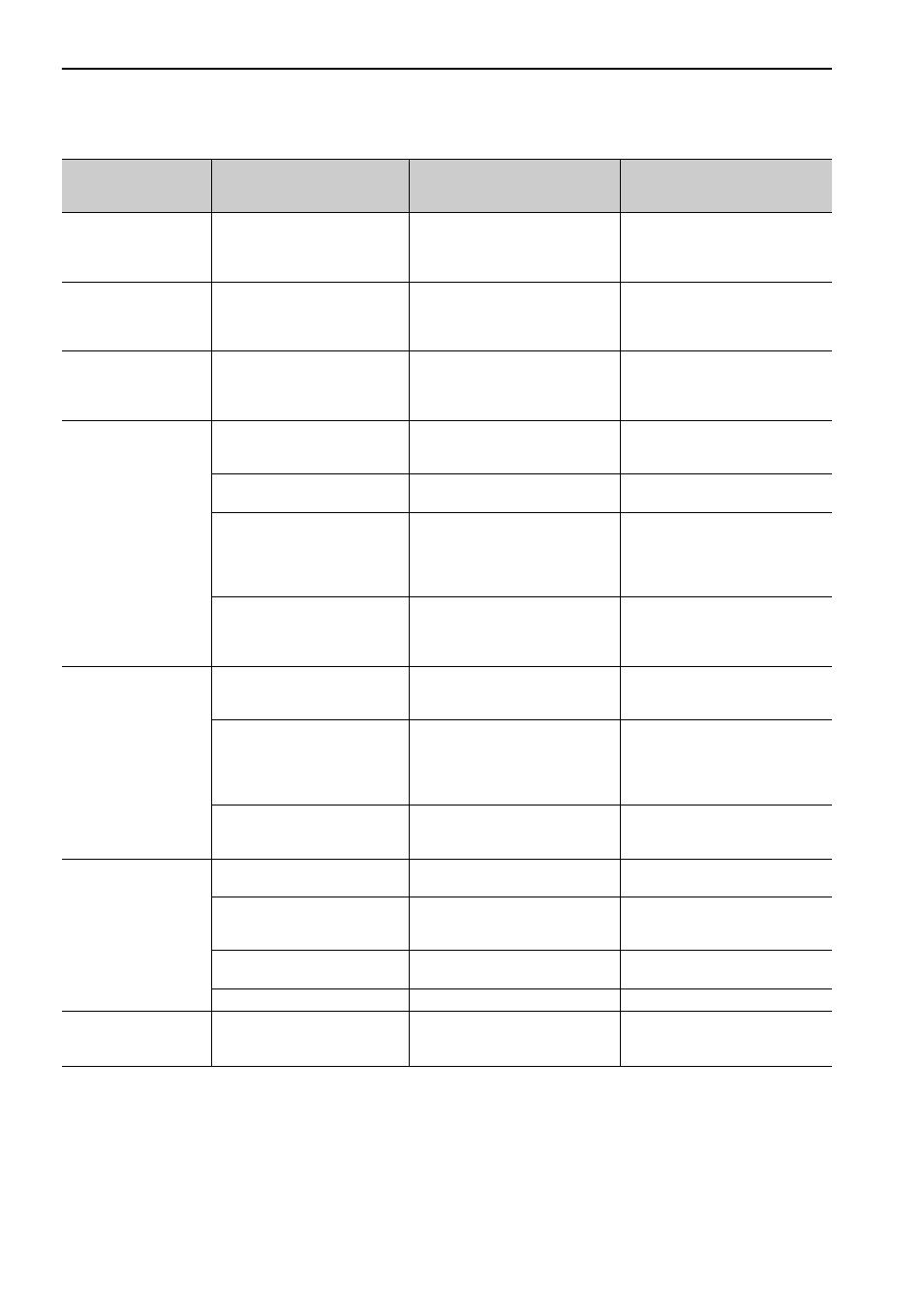
A.bF2:
System Alarm 2
A SERVOPACK fault occurred.
−
Turn the power supply OFF and
then ON again. If the alarm still
occurs, the SERVOPACK may be
faulty. Replace the SERVOPACK.
A.bF3
:
System Alarm 3
A SERVOPACK fault occurred.
−
Turn the power supply OFF and
then ON again. If the alarm still
occurs, the SERVOPACK may be
faulty. Replace the SERVOPACK.
A.bF4:
System Alarm 4
A SERVOPACK fault occurred.
−
Turn the power supply OFF and
then ON again. If the alarm still
occurs, the SERVOPACK may be
faulty. Replace the SERVOPACK.
A.C10:
Servo Overrun
Detected
(Detected when the
servomotor power is
ON.)
The order of phases U, V, and W
in the servomotor wiring is incor-
rect.
Check the motor wiring.
Confirm that the servomotor is cor-
rectly wired.
The setting of the motor phase
selection (Pn080.1) is incorrect.
Check the setting of Pn080.1.
Correct the setting of Pn080.1.
A linear scale fault occurred.
−
If the alarm still occurs after turning
the power OFF and then ON again,
even though the linear scale is cor-
rectly wired, the linear scale may be
faulty. Replace the linear scale.
A SERVOPACK fault occurred.
−
Turn the power supply OFF and
then ON again. If the alarm still
occurs, the SERVOPACK may be
faulty. Replace the SERVOPACK.
A.C20:
Phase Detection Error
The linear scale signal is weak.
Check the voltage of the linear scale
signal.
Fine-adjust the installation status of
the linear scale head, or replace the
linear scale.
The count-up direction of the lin-
ear scale does not match the for-
ward direction of the motor coil
assembly.
Check the setting of Pn080.1
(Motor Phase Selection).
Check the installation directions for
the linear scale and motor coil
assembly.
Change the setting of Pn080.1
(Motor Phase Selection).
Correctly reinstall the linear scale
and motor coil assembly.
The hall sensor signal is affected
by noise.
−
Correct the FG wiring and take
measures against noise for the hall
sensor wiring.
A.C21:
Hall Sensor Error
The hall sensor is protruding
from the motor magnetic way.
Check the hall sensor.
Correctly reinstall the motor coil
assembly or motor magnetic way.
The setting of the linear scale
pitch (Pn282) is incorrect.
Check the setting of the linear scale
pitch (Pn282).
Check the specifications of the lin-
ear scale and correct the value of
Pn282.
The hall sensor wiring is incor-
rect.
Check the hall sensor wiring.
Correct the hall sensor wiring.
A hall sensor fault occurred.
−
Replace the hall sensor.
A.C22:
Phase Information
Disagreement
The SERVOPACK phase data
does not match that of the linear
scale.
−
Execute polarity detection (Fn080).
(cont’d)
Alarm Number:
Alarm Name
(Alarm Description)
Cause
Investigative Actions
Corrective Actions