1 mechatrolink-iii communications settings, 1 setting switches s1, s2, and s3, 1) settings of the rotary switches s1 and s2 – Yaskawa Sigma-5 User Manual: Design and Maintenance - Linear Motors MECHATROLINK-III Communications Reference User Manual
Page 91: 2) settings of the dip switch s3, M-iii
4.1 MECHATROLINK-III Communications Settings
4-3
4
Op
er
at
io
n
4.1 MECHATROLINK-III Communications Settings
This section describes the switch settings necessary for MECHATROLINK-III communications.
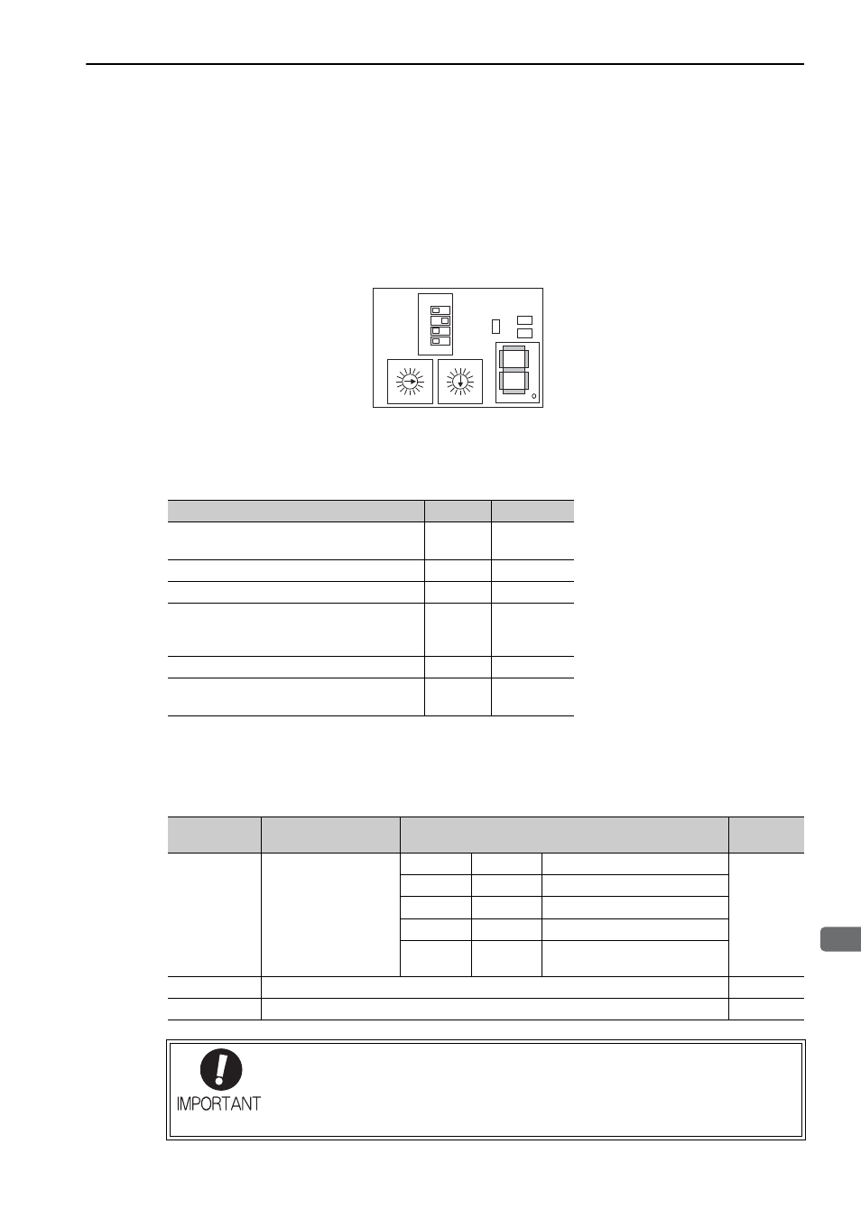
4.1.1 Setting Switches S1, S2, and S3
The DIP switch S3 is used to make the settings for MECHATROLINK-III communications.
The station address is set using the rotary switches S1 and S2.
(1) Settings of the Rotary Switches S1 and S2
Set the station address using the rotary switches S1 and S2.
(2) Settings of the DIP Switch S3
The following table shows the settings of the DIP switch (S3).
ᴾ
L1
L2
CN
4
3
5
2
6
1
7
C
8
0
F
9
E
A
D
B
S1
4
3
5
2
6
1
7
C
8
0
F
9
E
A
D
B
S2
ON
OFF
1234
S3
M-III
Station Address
S1
S2
00H to 02H: Disabled
(Do not use these addresses.)
0
0 to 2
03H (Factory setting)
0
3
04H
0
4
・
・
・
EFH
E
F
F0H to FFH: Disabled
(Do not use these addresses.)
F
0 to F
S3
Function
Setting
Factory
setting
Pins 1 and 2
Sets the number of
transmission bytes.
1
2
Number of transmission bytes
1: OFF
2: ON
OFF
OFF
16 byte
ON
OFF
32 byte
OFF
ON
48 byte
ON
ON
Reserved.
(Do not use this setting.)
Pin 3
Reserved. (Do not change.)
OFF
Pin 4
Reserved. (Do not change.)
OFF
• When using the MECHATROLINK-III standard servo profile, set the number of transmis-
sion bytes to either 32 or 48.
• When using the MECHATROLINK-II-compatible profile, set the number of transmission
bytes to either 16 or 32.
• Turn the power OFF and then ON again to enable the new settings.