Yaskawa Sigma-5 User Manual: Design and Maintenance - Linear Motors MECHATROLINK-III Communications Reference User Manual
Page 341
9.1 List of Parameters
9-43
9
Ap
pend
ix
91
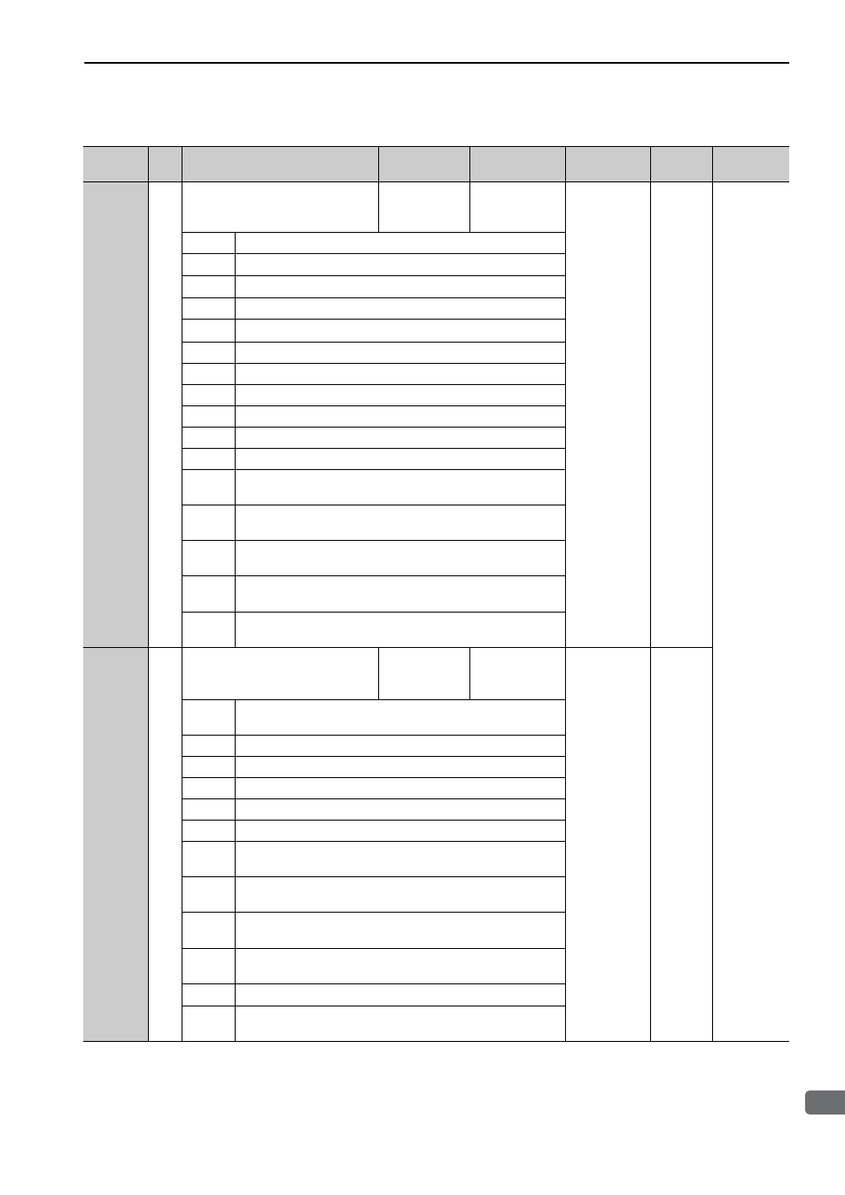
PnB22
4
Servo Command Status Field
Enabled/Disabled (read only)
–
0
0FFF3F33H
–
Command
Related
Parameters
Bit 0
CMD_PAUSE_CMP (1: Enabled)
Bit 1
CMD_CANCEL_CMP (1: Enabled)
Bit 2, 3
Reserved (0: Disabled)
Bit 4, 5
ACCFIL (1: Enabled)
Bit 6, 7
Reserved (0: Disabled)
Bit 8
L_CMP1 (1: Enabled)
Bit 9
L_CMP2 (1: Enabled)
Bit 10
POS_RDY (1: Enabled)
Bit 11
PON (1: Enabled)
Bit 12
M_RDY (1: Enabled)
Bit 13
SV_ON (1: Enabled)
Bit 14,
15
Reserved (0: Disabled)
Bit 16 to
19
SEL_MON1 (1: Enabled)
Bit 20 to
23
SEL_MON2 (1: Enabled)
Bit 24 to
27
SEL_MON3 (1: Enabled)
Bit 28 to
31
Reserved (0: Disabled)
92
PnB24
4
I/O Bit Enabled/Disabled (Output)
(read only)
–
–
007F01F0H
–
Bit
0 to 3
Reserved (0: Disabled)
Bit 4
V_PPI (1: Enabled)
Bit 5
P_PPI (1: Enabled)
Bit 6
P_CL (1: Enabled)
Bit 7
N_CL (1: Enabled)
Bit 8
G_SEL (1: Enabled)
Bit
9 to 11
G_SEL (0: Disabled)
Bit 12 to
15
Reserved (0: Disabled)
Bit 16 to
19
BANK_SEL (1: Enabled)
Bit 20 to
22
SO1 to SO3 (1: Enabled)
Bit 23
Reserved (0: Disabled)
Bit 24 to
31
Reserved (0: Disabled)
(cont’d)
Parameter
No.
Size
Name
Setting Range
Units
[Resolution]
Factory
Setting
When
Enabled
Classifica-
tion