Yaskawa Sigma-5 User Manual: Design and Maintenance - Linear Motors MECHATROLINK-III Communications Reference User Manual
Page 294
8.4 Troubleshooting Malfunction Based on Operation and Conditions of the Servomotor
8-33
8
Trou
blesh
ooting
Servomotor
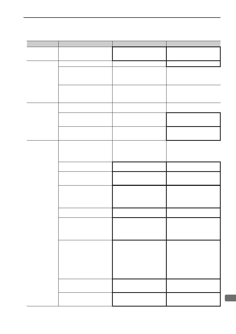
Speed Unstable
Wiring connection to servomotor is
defective.
Check connections of power line
(phases U, V, and W) and serial
converter unit connectors.
Tighten any loose terminals or con-
nectors and correct the wiring.
Servomotor
Moves Without
Reference Input
A SERVOPACK fault occurred.
−
Replace the SERVOPACK.
Linear scale counting up direction
and servomotor coil assembly for-
ward direction do not agree.
Check the directions.
Change the setting of Pn080.1
(Motor Phase Selection).
Match the linear scale direction and
servomotor direction.
Polarity detection is not performed
correctly.
Check if the value of Un004 (elec-
trical angle 2 from polarity origin)
at an arbitrary position is between
±10 degrees.
Correct the settings for the polarity
detection related parameter.
Dynamic Brake
Does Not Operate
Improper Pn001.0 setting
Check the setting for parameter
Pn001.0.
Correct the setting for parameter
Pn001.0.
DB resistor disconnected
Check if excessive mass, motor
overspeed, or DB frequently acti-
vated occurred.
Replace the SERVOPACK, and
reduce the load.
DB drive circuit fault
−
There is a defective component in
the DB circuit. Replace the SER-
VOPACK.
Abnormal Noise
from Servomotor
The servomotor largely vibrated
during execution of tuning-less
function.
Check the motor speed waveform.
Reduce the load so that the mass
ratio becomes within the allowable
value, or increase the load level or
lower the tuning level for the tun-
ing-less levels setting (Fn200).
Mounting is not secured.
Check if there are any loose mount-
ing screws.
Tighten the mounting screws.
Vibration source at the driven
machine.
Check for any foreign matter, dam-
age, or deformations on the machin-
ery's movable parts.
Contact the machine manufacturer.
Noise interference due to incorrect
I/O signal cable specifications.
The I/O signal cable must be tinned
annealed copper shielded twisted-
pair or screened unshielded twisted-
pair cable with a core of 0.12 mm
2
min.
Use the specified I/O signal cable.
Noise interference due to length of
I/O signal cable.
Check the length of the I/O signal
cable.
The I/O signal cable length must be
no more than 3 m.
Noise interference due to incorrect
cable specifications of linear scale
connection cables.
The linear scale connection cables
must be tinned annealed copper
shielded twisted-pair or screened
unshielded twisted-pair cable with a
core of 0.12 mm
2
min.
Use the specified linear scale con-
nection cables.
Noise interference due to length of
linear scale connection cables.
Check the length of the linear scale
connection cables.
The length of each cable must be
equal to or shorter than the maxi-
mum wiring length listed here.
• Connection cables for serial con-
verter unit: 20 m
• Connection cables for linear
scale: 15 m
• Connection cables for hall sensor:
15 m
Noise interference due to damaged
linear scale connection cables.
Check if the linear scale connection
cables are bent and the sheaths are
damaged.
Replace the linear scale connection
cables and correct the cable layout.
Excessive noise to the linear scale
connection cables.
Check if the linear scale connection
cables are bundled with a high-cur-
rent line or near a high-current line.
Correct the cable layout so that no
surge is applied.
(cont’d)
Problem
Probable Cause
Investigative Actions
Corrective Actions