3 mechatrolink-iii common parameters – Yaskawa Sigma-5 User Manual: Design and Maintenance - Linear Motors MECHATROLINK-III Communications Reference User Manual
Page 335
9.1 List of Parameters
9-37
9
Ap
pend
ix
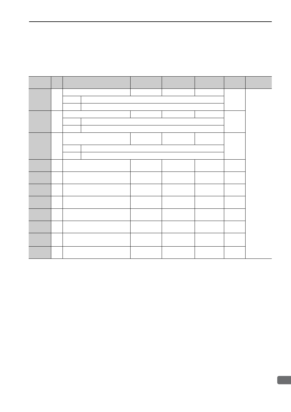
9.1.3 MECHATROLINK-III Common Parameters
The following list shows the common parameters used by all devices for MECHATROLINK-III. These com-
mon parameters are used to make settings from the host controller via MECHATROLINK communications.
Do not change settings with the digital operator or any other device.
Parameter
No.
Size
Name
Setting Range
Units
[Resolution]
Factory
Setting
When
Enabled
Classifica-
tion
01
PnA02
4
Encoder Type (read only)
0 to 1
–
–
–
Device
Information
Related
Parameters
0000H
Absolute encoder
0001H
Incremental encoder
02
PnA04
4
Motor Type (read only)
0 to 1
–
–
–
0000H
Rotational servomotor
0001H
Linear servomotor
03
PnA06
4
Semi-closed/Fully-closed Type
(read only)
0 to 1
–
–
–
0000H
Semi-closed
0001H
Fully-closed
04
PnA08
4
Rated Speed (read only)
0 to
FFFFFFFFH
mm/s
–
–
05
PnA0A
4
Maximum Output Speed (read only)
0 to
FFFFFFFFH
mm/s
–
–
06
PnA0C
4
Speed Multiplier (read only)
-1073741823 to
1073741823
–
–
–
07
PnA0E
4
Rated Force (read only)
0 to
FFFFFFFFH
N
–
–
08
PnA10
4
Maximum Output Force (read only)
0 to
FFFFFFFFH
N
–
–
09
PnA12
4
Force Multiplier (read only)
-1073741823 to
1073741823
–
–
–
0B
PnA16
4
Scale Pitch
0 to 65536000
nm
[0.01
μm]
*1
0
After
restart
0C
PnA18
4
Pulses per Scale Pitch (read only)
0 to
FFFFFFFFH
pulse/pitch
–
–
∗1. Set the units to multiples of 10.
Note: When using parameters that are enabled after restarting the SERVOPACK, a CONFIG command must be input or
the power must be turned OFF and then ON again.