8 speed limit detection signal (/vlt), 1) signals output during servomotor speed limit, 2) speed limit setting – Yaskawa Sigma-5 User Manual: Design and Maintenance - Linear Motors MECHATROLINK-III Communications Reference User Manual
Page 136
4 Operation
4.8.8 Speed Limit Detection Signal (/VLT)
4-48
4.8.8 Speed Limit Detection Signal (/VLT)
This function limits the speed of the servomotor to protect the machine.
A servomotor in force control is controlled to output the specified force, but the motor speed is not controlled.
Therefore, if an excessive reference force is set for the load force on the machinery side, the speed of the ser-
vomotor may increase greatly. If that may occur, use this function to limit the speed.
Note: The actual limit value of motor speed depends on the load conditions of the servomotor.
Refer to the following parameters for speed limit.
(1) Signals Output during Servomotor Speed Limit
The following signal is output when the motor speed reaches the limit speed.
Note: Use parameter Pn50F.1 to allocate the /VLT signal for use. For details, refer to 3.3.2 Output Signal Allocations.
(2) Speed Limit Setting
Select the speed limit mode with Pn002.1.
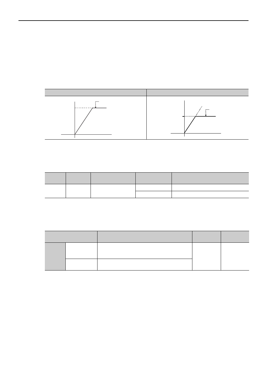
With No Speed Limit
With Speed Limit
Motor speed
Time
Maximum speed
Danger of damage due to
critical speed.
Motor speed
Limiting speed
Safe operation with
speed limit.
Time
Type
Signal
Name
Connector
Pin Number
Setting
Meaning
Output
/VLT
Must be allocated
ON (closed)
Servomotor speed limit being applied.
OFF (open)
Servomotor speed limit not being applied.
Parameter
Meaning
When
Enabled
Classification
Pn002
n.
0
[Factory setting]
VLIM (the speed limit value during force control) is
not available. Uses the value set in Pn480 as the speed
limit (internal speed limit function).
After restart
Setup
n.
1
VLIM operates as the speed limit value (external speed
limit function).