3 checking output force limiting during operation – Yaskawa Sigma-5 User Manual: Design and Maintenance - Linear Motors MECHATROLINK-III Communications Reference User Manual
Page 125
4.6 Limiting Force
4-37
4
Op
er
at
io
n
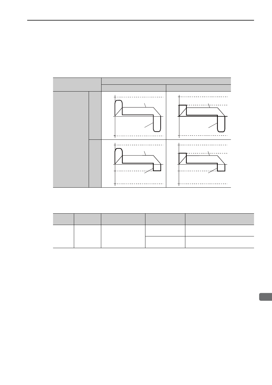
(3) Changes in Output Force during External Force Limiting
The following diagrams show the change in output force when the internal force limit is set to 800%.
In this example, the servomotor movement direction is Pn000.0 = 0 (Linear scale counting up direction is
regarded as the forward run).
4.6.3 Checking Output Force Limiting during Operation
The following signal can be output to indicate that the servomotor output force is being limited.
Note: Use parameter Pn50F.0 to allocate the /CLT signal for use. For details, refer to 3.3.2 Output Signal Allocations.
/P-CL
OFF
ON
/N-CL
OFF
ON
Pn483
Pn484
0
Force
Speed
Pn484
0
Pn404
Pn483
Force
Speed
0
Pn484
Pn405
Pn483
Force
Speed
0
Pn484
Pn405
Pn404
Pn483
Force
Speed
Type
Signal Name
Connector
Pin Number
Setting
Meaning
Output
/CLT
Must be allocated
ON (closed)
Servomotor output force is being lim-
ited.
OFF (open)
Servomotor output force is not being
limited.