Yaskawa Sigma-5 User Manual: Design and Maintenance - Linear Motors MECHATROLINK-III Communications Reference User Manual
Page 303
9.1 List of Parameters
9-5
9
Ap
pend
ix
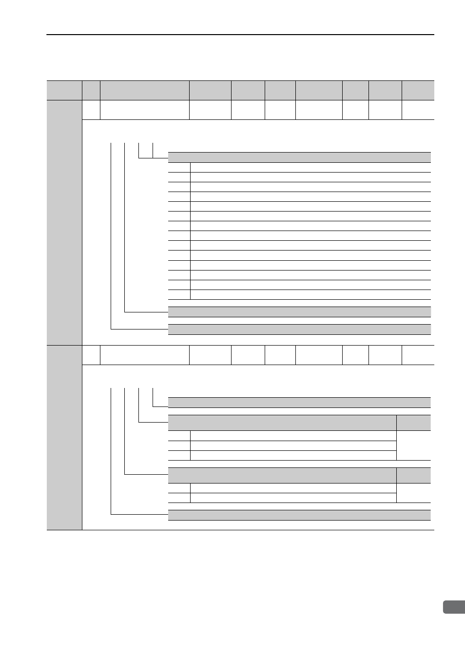
Pn007
2
Application Function Select
Switch 7
0000 to 005F
−
0000
Immediately
Setup
−
5.1.3
Pn008
2
Application Function Select
Switch 8
0000 to 7121
−
4000
After restart
Setup
−
−
(cont’d)
Parameter
No.
Size
Name
Setting
Range
Units
Factory
Setting
When
Enabled
Classi-
fication
Profile
Reference
Section
Analog Monitor 2 Signal Selection
00
Motor moving speed (1 V / 1000 mm/s)
01
Speed reference (1 V / 1000 mm/s)
02
Force reference (1 V/100% rated force)
03
Position error (0.05 V/1 reference unit)
04
Position amplifier error (after electronic gears) (0.05 V/ 1 linear scale pulse unit)
05
Position reference speed (1 V / 1000 mm/s)
06
Reserved (Do not use.)
07
Reserved (Do not use.)
08
Positioning completion (positioning completed: 5 V, positioning not completed: 0 V)
09
Speed feedforward (1 V / 1000 mm/s)
0A
Force feedforward (1 V/100% rated force)
0B
Active gain (1st gain: 1 V, 2nd gain: 2 V)
0C
Completion of position reference (completed: 5 V not completed: 0 V)
0D
Reserved (Do not use.)
Reserved (Do not change.)
Reserved (Do not change.)
4th 3rd 2nd 1st
digit digit digit digit
n.
Reserved (Do not change.)
Function Selection for Undervoltage
Reference
Section
0
Does not detect undervoltage.
4.3.8
1
Detects warning and limits force by host controller.
2
Detects warning and limits force by Pn424 and Pn425. (Only in the SERVOPACK)
Warning Detection Selection
Reference
Section
0
Detects warning.
8.2.1
1
Does not detect warning (except for A.971).
Reserved (Do not change.)
4th 3rd 2nd 1st
digit digit digit digit
n.