Yaskawa Sigma-5 User Manual: Design and Maintenance - Linear Motors MECHATROLINK-III Communications Reference User Manual
Page 340
9 Appendix
9.1.3 MECHATROLINK-III Common Parameters
9-42
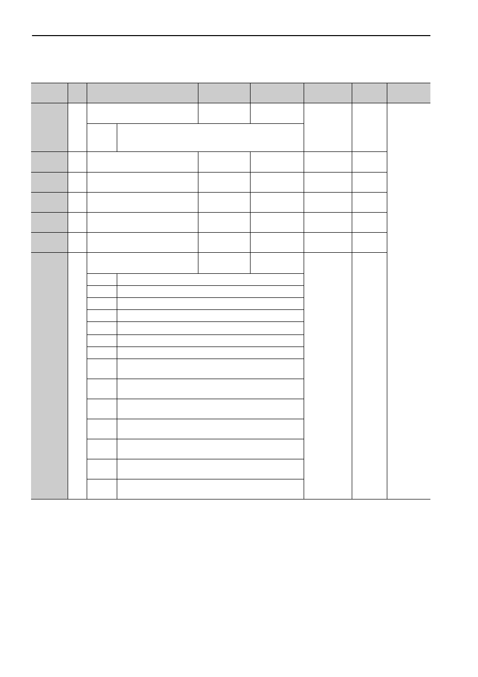
8A
PnB14
4
Monitor Selection for SEL_MON2
(CMN2)
0 to 6
–
0
Immedi-
ately
Command
Related
Parameters
0000H
to
0006H
Same as Monitor Selection for SEL_MON1.
8B
PnB16
4
Origin Detection Range
0 to 250
1 reference unit
10
Immedi-
ately
8C
PnB18
4
Forward Force Limit
0 to 800
1%
100
Immedi-
ately
8D
PnB1A
4
Reverse Force Limit
0 to 800
1%
100
Immedi-
ately
8E
PnB1C
4
Zero Speed Detection Range
1000 to
10000000
10
-3
mm/s
20000
Immedi-
ately
8F
PnB1E
4
Speed Coincidence Signal Output
Width (read only)
0 to 100000
10
-3
mm/s
10000
Immedi-
ately
90
PnB20
4
Servo Command Control Field
Enabled/Disabled (read only)
–
–
0FFF3F3FH
–
Bit 0
CMD_PAUSE (1: Enabled)
Bit 1
CMD_CANCEL (1: Enabled)
Bit 2, 3
STOP_MODE (1: Enabled)
Bit 4, 5
ACCFIL (1: Enabled)
Bit 6, 7
Reserved (0: Disabled)
Bit 8
LT_REQ1 (1: Enabled)
Bit 9
LT_REQ2 (1: Enabled)
Bit 10,
11
LT_SEL1 (1: Enabled)
Bit 12,
13
LT_SEL2 (1: Enabled)
Bit 14,
15
Reserved (0: Disabled)
Bit 16 to
19
SEL_MON1 (1: Enabled)
Bit 20 to
23
SEL_MON2 (1: Enabled)
Bit 24 to
27
SEL_MON3 (1: Enabled)
Bit 28 to
31
Reserved (0: Disabled)
(cont’d)
Parameter
No.
Size
Name
Setting Range
Units
[Resolution]
Factory
Setting
When
Enabled
Classifica-
tion