4 encoder output pulses, 1) signals, 2) output phase form – Yaskawa Sigma-5 User Manual: Design and Maintenance - Linear Motors MECHATROLINK-III Communications Reference User Manual
Page 114: Linear
4 Operation
4.4.4 Encoder Output Pulses
4-26
4.4.4 Encoder Output Pulses
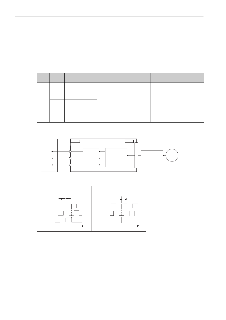
The encoder pulse output is a signal that is output from the linear scale and processed inside the SERVO-
PACK. It is then output externally in the form of two phase pulse signal (phases A and B) with a 90
° phase dif-
ferential. It is used as the position feedback to the host controller.
Signals and output phase form are as shown below.
(1) Signals
∗ For details on the phase C, refer to (3) Encoder Output Pulse Signals from SERVOPACK with a Linear Scale by Ren-
ishaw plc.
(2) Output Phase Form
Note: The pulse width for phase C (origin pulse) changes according to the setting of the encoder output resolution (Pn281)
and becomes the same as that for phase A.
Even in reverse movement mode (Pn000.0 = 1), the output phase form is the same as that for the standard setting
(Pn000.0 = 0) above.
Type
Signal
Name
Connector
Pin Number
Name
Remarks
Output
PAO
CN1-17
Encoder output pulse: phase A
The resolution of the pulse output
from the SERVOPACK to the host
controller is set in the parameter for
the encoder output resolution
(Pn281). Phase A and phase B are
different from each other in phase by
an electric angle of 90
°.
/PAO
CN1-18
PBO
CN1-19
Encoder output pulse: phase B
/PBO
CN1-20
PCO
CN1-21
Encoder output pulse: phase C
*
−
/PCO
CN1-22
CN1
CN2
PAO
PBO
PCO
SERVOPACK
Host controller
Serial
data
Linear
scale
Converts
serial
data to
pulse.
Dividing
circuit
(Pn281)
ENC
Serial
converter unit
Linear
Phase A
Phase B
Phase C
90°
t
Phase A
Phase B
Phase C
90°
t
Forward movement (phase B leads by 90
°) Reverse movement (phase A leads by 90°)