6 linear scale connection, 1 linear scale signal (cn2) names and functions, 2 serial converter unit – Yaskawa Sigma-5 User Manual: Design and Maintenance - Linear Motors MECHATROLINK-III Communications Reference User Manual
Page 75: 1) model: jzdp-d00 - -e
3.6 Linear Scale Connection
3-27
3
Wirin
g and
Co
nnectio
n
3.6 Linear Scale Connection
This section describes the linear scale signal (CN2) names, functions, and connection examples.
3.6.1 Linear Scale Signal (CN2) Names and Functions
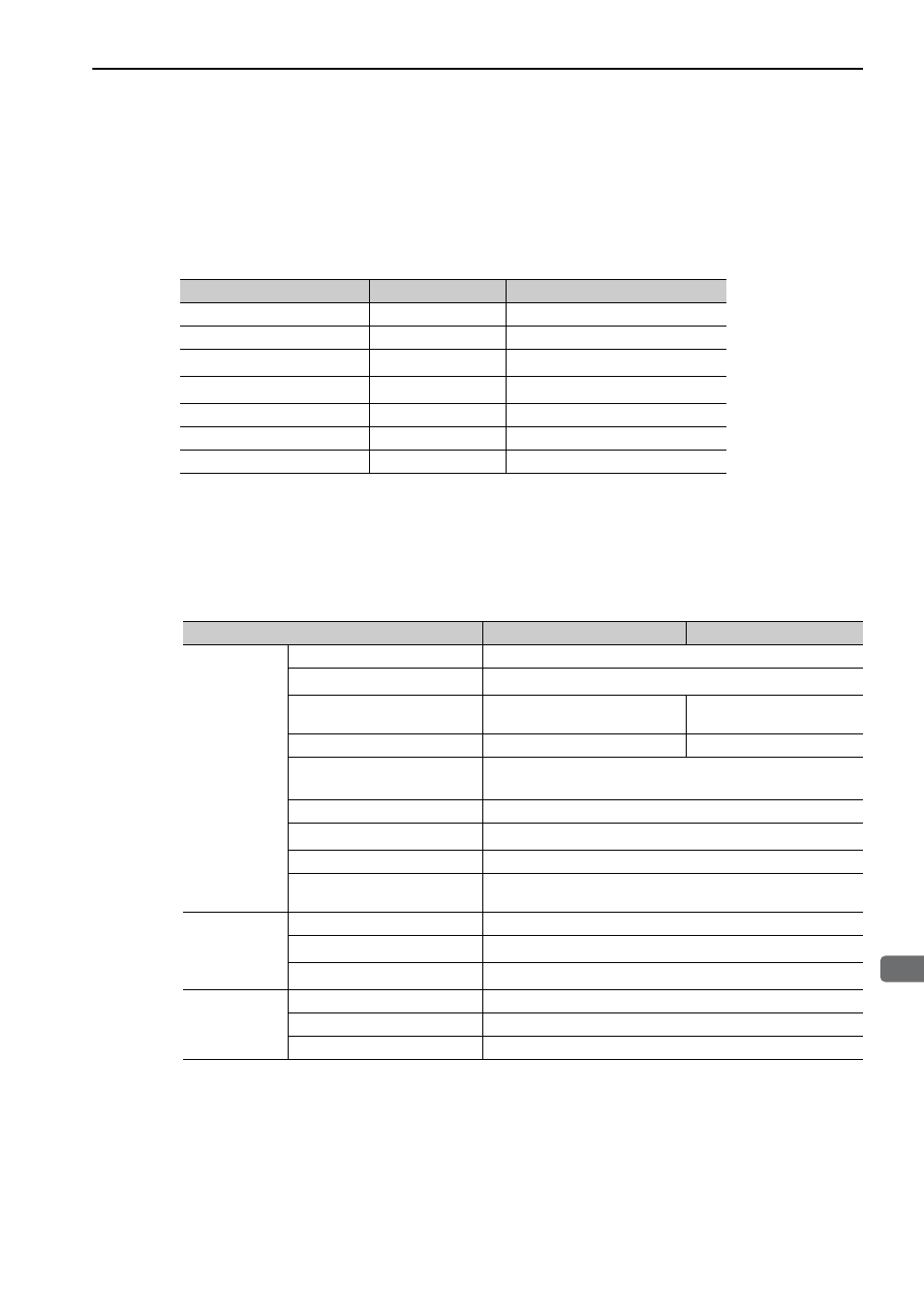
The following table shows the names and functions of linear scale signals (CN2).
∗ Do not use pins 3 and 4.
3.6.2 Serial Converter Unit
(1) Model: JZDP-D00 -
-E
The following table shows the characteristics and specifications of the serial converter unit.
* 1. The current consumption of the linear scale and the hall sensor is not included in this value.
The current consumption of the linear scale and the hall sensor must be taken into consideration for
the current capacity of host controller that supplies the power. (The current consumption of the hall
sensor is about 40 mA.)
* 2. Input a value within the specified range. Otherwise, incorrect position information is output, and the
device may be damaged.
* 3. The transmission is enabled 100 to 300 ms after the power turns ON.
Signal Name
Pin No.
Function
PG 5 V
1
Linear scale power supply +5 V
PG 0 V
2
Linear scale power supply 0 V
–
3
*
–
–
4
*
–
PS
5
Serial data (+)
/PS
6
Serial data (-)
Shield
Shell
–
Items
JZDP-D00 -
-E
JZDP-G00 -
-E
Electrical
Characteristics
Power Supply Voltage
+5.0 V
±5%, ripple content 5% max.
Current Consumption
∗1
120 mA Typ. 350 mA max.
Signal Resolution
1/256 pitch of input 2-phase sine
wave
1/4096 pitch of input 2-phase
sine wave pitch
Max. Response Frequency
250 kHz
100 kHz
Analog Input Signals
∗2
(cos, sin, Ref)
Differential input amplitude: 0.4 V to 1.2 V
Input signal level: 1.5 V to 3.5 V
Hall Sensor Input Signal
CMOS level
Output Signal
∗3
Position data, hall sensor information, alarms
Output Method
Serial data communications
Output Circuit
Balanced type transceiver (SN75LBC176 or the equivalent), inter-
nal terminating resistor: 120
Ω
Mechanical
Characteristics
Approx. Mass
150 g
Vibration Resistance
98 m/s
2
max. (10 to 2500 Hz) in three directions
Shock Resistance
980 m/s
2
, (11 ms) two times in three directions
Environmental
Conditions
Surrounding Air Temperature 0
°C to 55 °C
Storage Temperature
-20
°C to +80 °C
Humidity
20% to 90%RH (without condensation)