Yaskawa Sigma-5 User Manual: Design and Maintenance - Linear Motors MECHATROLINK-III Communications Reference User Manual
Page 328
9 Appendix
9.1.2 Parameters
9-30
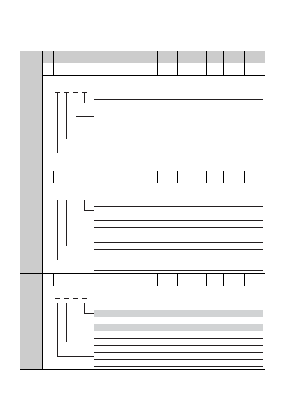
Pn82C
2
Option Field Allocation 3
0000 to
1F1F
–
1F1E
After restart
Setup
M2
*10
–
Pn82D
2
Option Field Allocation 4
0000 to
1F1C
–
0000
After restart
Setup
M2
*10
–
Pn82E
2
Option Field Allocation 5
0000 to
1D1F
–
0000
After restart
Setup
M2
*10
–
∗10. This parameter is enabled only for MECHATROLINK-II-compatible profile.
(cont’d)
Parameter
No.
Size
Name
Setting
Range
Units
Factory
Setting
When
Enabled
Classi-
fication
Profile
Reference
Section
4th
digit
3rd
digit
2nd
digit
1st
digit
n.
0 to F
P_CL bit position
0
1
Disables P_CL bit allocation.
Enables P_CL bit allocation.
0 to F
N_CL bit position
0
1
Disables N_CL bit allocation.
Enables N_CL bit allocation.
4th
digit
3rd
digit
2nd
digit
1st
digit
n.
0 to C
BANK_SEL1 bit position
0
1
Disables BANK_SEL1 bit allocation.
Enables BANK_SEL1 bit allocation.
0 to F
LT_DISABLE bit position
0
1
Disables LT_DISABLE bit allocation.
Enables LT_DISABLE bit allocation.
4th
digit
3rd
digit
2nd
digit
1st
digit
n.
0 to D
OUT_SIGNAL bit position
0
1
Disables OUT_SIGNAL bit allocation.
Enables OUT_SIGNAL bit allocation.
Reserved (Do not change.)
Reserved (Do not change.)