ATEIS UAPg2 User Manual
Page 130
UAPG2 MANUAL
Version EN.24
130
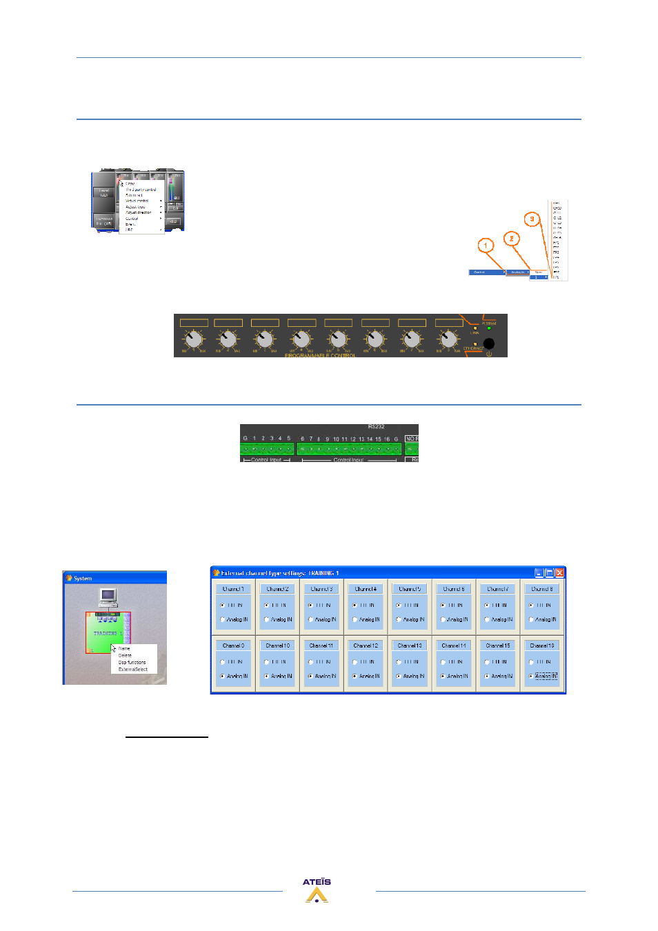
Use front knobs
Right click on the software adjustments you want to pilot with the control input and choose control
option:
1) Type of control you can assign to this software control (adjustments)
2) Name of the UAPG2 in the system
3) Connector channel number (control input 9 to 16 defined as analog
input…) FP = Front Panel knob
FP1 FP2 FP3 FP4 FP5 FP6 FP7 FP8
Use Control inputs
First you have to define if rear control input is logic or analog input.
You must be unconnected to do that.
On the system window in the working area right click on the desired UAPG2 (if you have several
UAPG2 in a system) and choose “ExternalSelect” option. Then in the “External channel type settings:
#name of the UAPG2#”, select for each connector if it is a TTL IN (logic) or an Analogical IN.
If you set the others channel ( 9 to 16 ) in TTL IN mode, than you have to configure the groups 9 to
16 in the Logic IN window (that means assign TTLin 9 to group 9, and TTLin 10 to group 10, etc).
Caution: You cannot mix the TTL and Analogue freely. In order, all the TTL must be before all the
analogue.