ATEIS UAPg2 User Manual
Page 16
UAPG2 MANUAL
Version EN.24
16
HARDWARE DESCRIPTION
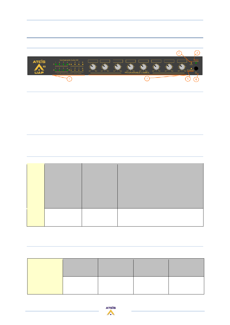
FRONT PANEL
1) CONFIGURABLE AUDIO I/O
Inside the UAPG2 you have 4 audio slots (named A, B, C and D). Each of these audios slots receives
either 4 audio inputs channels or 4 audio outputs channels. When you switch on the UAPG2 you can
see which kind of audio card is fitted in each slots:
•
Green LEDs mean INPUTs
•
Yellow LEDs mean OUTPUTs
When a signal passes through an input or an output the corresponding LED will blink.
2) PROGRAMMABLE CONTROL SECTION (PROGRAMMABLE FRONT KNOB)
Eights front knob allow quick adjustment of every analogical audio treatment. Simply assign what
you need. To learn how to proceed, see the HOW TO use front panel knob.
3) POWER LED
Lights when the UAPG2 is switched on.
Normal status
Standby status
Error status
-The UAPg2 has no design inside.
-The design inside the UAPg2 does not match
with the physical installation.
-If the link led is off :
The UAPg2 has no input link
Power
LED
The LED grows
bright in green
The LED grows
bright in red
The LED flicks in red and green
4) LINK LED
Light when the UAPG2 is linked in a UAPG2 system (several UAPG2 connected)
The link is
successful
Unconnected line
Already on-line but
don't configured
Already on-line but
LVDS receive error
Linking LED
The LED green
grows bright
The LED has no
bright
Twinkle 2
times
Twinkle 3
times