ATEIS UAPg2 User Manual
Page 132
UAPG2 MANUAL
Version EN.24
132
Logic inputs in binary mode (group, only for selector component or presets selection)
The binary mode means use Logic inputs as “bit” for different choice.
The analog/logic input must be set as TTL IN in the external settings.
To use the TTL IN in binary mode, several TTL IN must be assigned to a group.
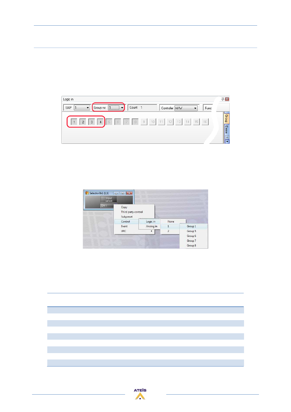
Open the Logic IN floating window:
Assign several TTL IN to a group. In this example the TTL IN 2,3, and 4 have been unassigned to the
group 2,3 and 4 (to make them free). Then all of them have been assigned to the group 1.
The TTL IN number in black means "TTL IN selected for the group".
Second step right click on the selector you want to pilot with the control input and choose control
option:
1)
Select Logic IN
2)
Select the name of the UAPG2
3)
Select the "multi-logic" group
The value of the controlled parameters will depend of the binary value of the group.
TTL IN 4
MSB
TTL IN 3
TTL IN 2
TTL IN 1
LSB
Binary value
Selector
position
0
0
0
0
0000
1
0
0
0
1
0001
2
0
0
1
0
0010
3
0
0
1
1
0011
4
0
1
0
0
0100
5
0
1
0
1
0101
6
0
1
1
0
0110
7
...
...
...
...
...
...
1
1
1
1
1111
16
Now if you open the Machine tab of the Logic In floating window you can see the multi-logic selector