ATEIS UAPg2 User Manual
Page 18
UAPG2 MANUAL
Version EN.24
18
4) LINK CONNECTORS
If you want to put several UAPG2 in your rack (increase the number of input/output or remote
controllers) simply use straight CAT5 cable to connect “digilink” output to the “digilink” input of the
next sub-UAPG2. Close the loop by connecting the last UAPG2 to the first one.
Note: this is not a network but a link: The maximum cable length is 10 meters between two UAPG2.
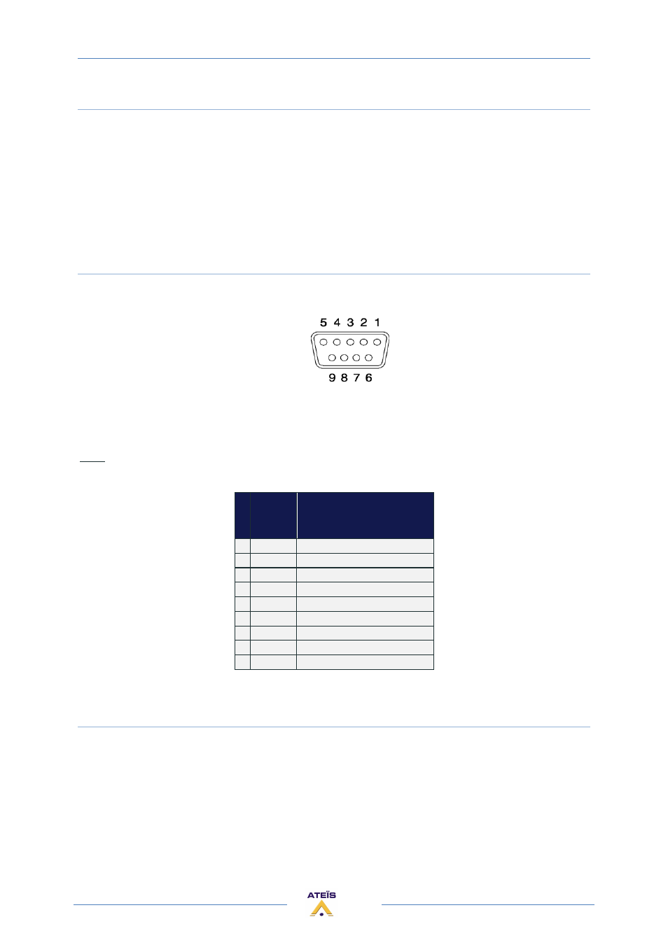
5) RS232 CONNECTOR
Connect third party device (Crestron, AMX, VITY) to pilot some desired features of your UAPG2
system by using the Ateïs Third party protocol.
At the rear side of the UAPG2 you also find a DB9f connector for RS232 data communication. This
port can be used for transparent RS232 data multipoint communication through the network (for
using with IDA4) or for 3rd party control applications.
Note:
RS232 does support cable lengths up to 15 m.
P
i
n
Signal
Text
1
CD
carrier detect (n.c.)
2
RXD
receive data
3
TXD
transmit data
4
DTR
data terminal ready (n.c.)
5
GND
ground
6
DSR
data set ready (n.c.)
7
RTS
request to send (n.c)
8
CTS
clear to send (n.c.)
9
RI
ring indicator (n.c.)
(n.c):non connected
6) ETHERNET (RJ45) CONNECTOR
For connecting the UAPG2 in a TCP/IP based network or directly to a computer:
•
To load design in a UAPG2 system
•
To pilot UAPG2 system
•
To monitor UAPG2 system