Mapping cos values to egress queues, Table 13: cos priority levels – Microsens MS453490M Management Guide User Manual
Page 225
C
HAPTER
11
| Class of Service
Layer 2 Queue Settings
– 225 –
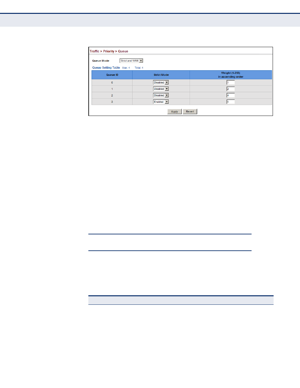
Figure 112: Setting the Queue Mode (Strict and WRR)
M
APPING
C
O
S V
ALUES
TO
E
GRESS
Q
UEUES
Use the Traffic > Priority > PHB to Queue page to specify the hardware
output queues to use based on the internal per-hop behavior value. (For
more information on exact manner in which the ingress priority tags are
mapped to egress queues for internal processing, see
Priorities to Internal DSCP Values" on page 232
).
The switch processes Class of Service (CoS) priority tagged traffic by using
four priority queues for each port, with service schedules based on strict
priority, Shaped Deficit Weighted Round-Robin (SDWRR), or a combination
of strict and weighted queuing. Up to eight separate traffic priorities are
defined in IEEE 802.1p. Default priority levels are assigned according to
recommendations in the IEEE 802.1p standard as shown in
. The
following table indicates the default mapping of internal per-hop behavior
to the hardware queues. The actual mapping may differ if the CoS priorities
to internal DSCP values have been modified (
).
The priority levels recommended in the IEEE 802.1p standard for various
network applications are shown in
. However, priority levels can be
mapped to the switch’s output queues in any way that benefits application
traffic for the network.
Table 12: IEEE 802.1p Egress Queue Priority Mapping
Priority
0
1
2
3
4
5
6
7
Queue
1
0
0
1
2
2
3
3
Table 13: CoS Priority Levels
Priority Level
Traffic Type
1
Background
2
(Spare)
0 (default)
Best Effort
3
Excellent Effort
4
Controlled Load
5
Video, less than 100 milliseconds latency and jitter