Per channel control knobs, High resolution meters, 114 high resolution meters – Metric Halo Mobile I/O User Manual
Page 114: Mic/line indicator, 114 9.7. front panel control knob, Mic/line indicator modes
ULN/LIO-8 Front Panel Guide
114
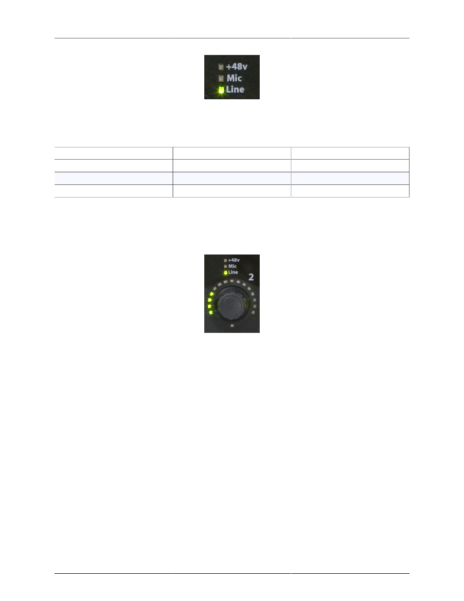
Figure 9.6: Mic/Line Indicator
The Mic and Line indicators are utilized as a group and are illuminated to indicate the following input modes:
Table 9.1. Mic/Line Indicator Modes
Mic
Line
Mode
On (green)
Off
Input from Mic Pre Input
Off
On (green)
Input from Line Input
On (green)
On (green)
Mic Send/Return Mode
Per Channel Control Knobs
The eight numbered knobs are detented rotary encoders with integrated push button tact switches. Each knob
has a ring of 15 bi-color (red/green) LEDs around it and a bi-color “flexi” led below it. Both the ring of LEDs
and the “flexi” LED may be used for different purposes depending on the current control mode.
Figure 9.7: Front Panel Control Knob
The operational effect of the knobs depends on the currently selected control mode for the front panel. When
the currently selected control mode is a mode that controls channel parameters (e.g. Input, Link, +48, Input
Trim and Output Trim) each knob is associated with the channel number indicated next to the knob. When
the currently selected control mode is a global mode (e.g. Monitor, Preset, and U/M), then the knob reflects
the associated selection number for the mode. See below for more details.
The data displayed in the indicator ring around each knob is also determined by the currently selected mode.
The indicator ring supports displaying the following kinds of data:
• High Resolution “Digital Dual Vernier™” gain readout
• Input Meters
• Selected State for Mode Selection (Monitor, Preset, and U/M Modes)
• Link Status Indication (Link Mode)
The details of each of these indication modes will be discussed in the dedicated control mode sections of the
documentation below.
High Resolution Meters
The Front Panel provides 16 meter bars with 15 segments per bar. Every segment is a bi-color LED with
programmable color. The meters are grouped into two 8 meter blocks; the block on the left hand side is used for
Analog Input meters and the block on the right is used for Analog Output meters. By default, the 15 segments