Analog output control, Lock indicators – Metric Halo Mobile I/O User Manual
Page 155
MIO Console Overview
155
WARNING: You MUST power the 2882 from an external power source BEFORE enabling High Pow-
er mode. FAILURE TO USE AN EXTERNAL POWER SOURCE IN HIGH POWER MODE MAY CAUSE
DAMAGE TO YOUR COMPUTER.
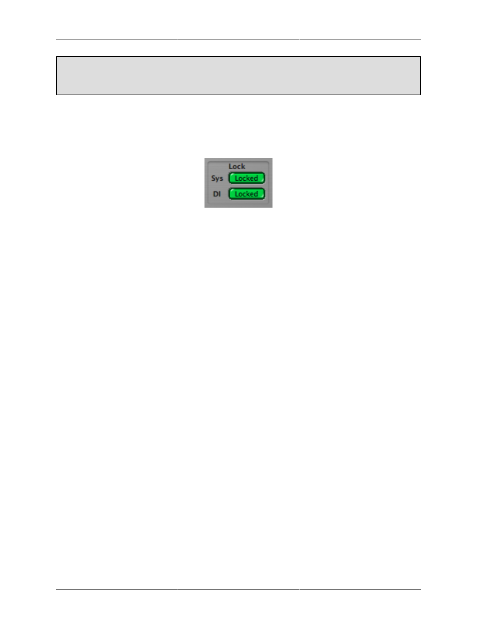
– The Lock indicators show which elements of the Mobile I/O clocking system are properly locked. The
clocking system must be locked for the unit to behave as expected. If the system is not locked, audio will play
at the wrong rate and will be distorted or noisy. Under normal circumstances, the system should always be
locked, but if you have selected an external clock source and the clock signal is not present, corrupted or out-
of-range, the system may unlock. There are indicators for the system and the digital input.
Figure 11.26: Lock Indicators
Analog Output Control
The bottom half of the panel is dedicated to the hardware outputs of the Mobile I/O. Much like the analog
inputs, each of the eight analog outputs has a set of controls associated with it. The controls are similar to
the analog input controls. If these controls are “grayed out”, it is because they are referenced by the Monitor
Controller, which removes direct control from this panel. If you want to control the analog output from this
panel, you must remove the Monitor Control output path that references it. Each output channel (except the
ULN-2, as it has analog front panel controls) has:
– Parameter Pop-up control: The Parameter Pop-up control allows you to save, recall, and manage the param-
eters associated with an analog output in one place. The control is documented in detail in the
section of this chapter. All presets are automatically shared between all of the output channels.
– Level Standard pop-up menu: This control allows you to select the output level for the channel. The available
choices are:
• Line +4 —
• 2882: This format supports output levels up to +26 dBu. The standard setting with the trim knob set
to 0 dB yields a +24 dBu output when the digital signal driving the DAC is 0 dBFS. This corresponds
to +4 dBu nominal with 20 dB of digital headroom.
• LIO-8: This format supports output levels up to +18.5 dBu (jumper selectable to 24.5 dBu). The stan-
dard setting with the trim knob set to 0 dB yields a +18.5 dBu output when the digital signal driving
the DAC is 0 dBFS. This corresponds to +4 dBu nominal with 20 dB of digital headroom.
• ULN-8: This format supports output levels up to +18.5 dBu (jumper selectable to 24.5 dBu). The
standard setting with the trim knob set to 0 dB yields a +18.5 dBu output when the digital signal
driving the DAC is 0 dBFS. This corresponds to +4 dBu nominal with 20 dB of digital headroom.
You can use the trim knob to adjust the analog output level to be consistent with the needs of other
audio gear. The output impedance is approximately 50 Ω on the 2882 and 5 Ω on the LIO-8/ULN-8.
This format is appropriate for interfacing with professional audio equipment.
• Line -10 —
• 2882: This format supports a nominal output level of -10 dBV with 20 dB of digital headroom. The
output impedance is approximately 50 Ω.
• LIO-8: This format supports a nominal output level of -10 dBV with 20 dB of digital headroom. The
output impedance is approximately 5 Ω.
• ULN-8: This format supports a nominal output level of -10 dBV with 20 dB of digital headroom. The
output impedance is approximately 5 Ω.