System status indicators, Aes status indicators, 116 aes status indicators – Metric Halo Mobile I/O User Manual
Page 116: Negative gain display, 116 9.12. system status, 116 9.13. aes indicators
ULN/LIO-8 Front Panel Guide
116
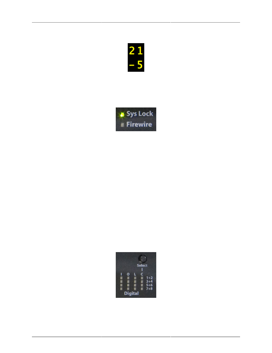
If the gain being read out is -21.5 dB, then the display will look like:
Figure 9.11: Negative Gain Display
System Status Indicators
The Front Panel has two system status indicators to let you know if the box has detected a valid FireWire
connection and to let you know if the System’s internal PLL is locked.
Figure 9.12: System Status
The FireWire Indicator will be illuminated green whenever the box detects a valid sequence of FireWire
isochronous cycles on the connected FireWire bus. When the FireWire indicator is illuminated, it means that
the box is communicating with the FireWire bus properly.
The Sys Lock indicator will be illuminated green when the internal PLL is locked and within normal operating
ranges. This indicator lets you know if the box is locked to a valid clock source.
AES Status Indicators
There are a total of 16 indicators in this area. There are 4 columns and 4 rows. Each row represents a different
AES port/cable. Each port carries two channels of audio, so the columns are labeled 1+2, 3+4, 5+6 and 7+8.
The columns provide indicators for 4 different types of status:
• I — Input Level for corresponding port
• O — Output Level for corresponding port
• L — Input receiver Locked for corresponding port
• C — Input port selected as AES clock source
The Input Level and Output Level indicators show the highest level on the channel pair via brightness and
color. They can be treated as “signal present indicators”.
Figure 9.13: AES Indicators
The Locked indicator is illuminated when the AES receiver for the corresponding input port detects and locks
to a valid AES signal. Please note that this does NOT indicate that the input is locked at the same rate as the