I.14. phantom supply cable and ch. 1-4 connectors, 349 i.15. installing the ch. 1-4 mic pre board – Metric Halo Mobile I/O User Manual
Page 349
ULN-R Installation Guide
349
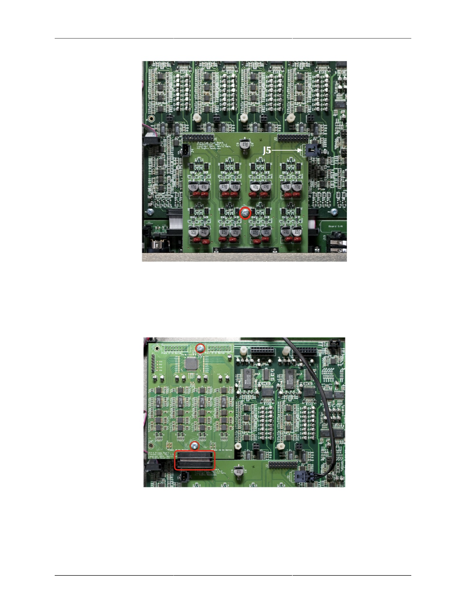
Figure I.14: Phantom Supply Cable and Ch. 1-4 Connectors
8. Install the mic pre board, making sure that the pins on the bottom of the board line up with the sockets
highlighted in the picture above. You must install the channel 1-4 board in this position. Use two Phillips
head screws to secure the mic pre board and dab them with caulk. Fit the ribbon cable jumper between
the mic pre and DB25 connector board, making sure that the pins are lined up.
Figure I.15: Installing the Ch. 1-4 Mic Pre Board
9. If you are installing the channel 5-8 mic pre kit, install it in the sockets next to the channel 1-4 board,
making sure the pins are properly seated. Use four Phillips head screws to secure the mic pre board
and dab them with caulk. Fit the ribbon cable jumper between the mic pre and DB25 connector board,
making sure that the pins are lined up.