I.8. side screw placement, with rack ear, 347 i.9. side screw placement, no rack ear, 347 i.10. mic in blank plate – Metric Halo Mobile I/O User Manual
Page 347: 347 i.11. db25 connector board fitted
ULN-R Installation Guide
347
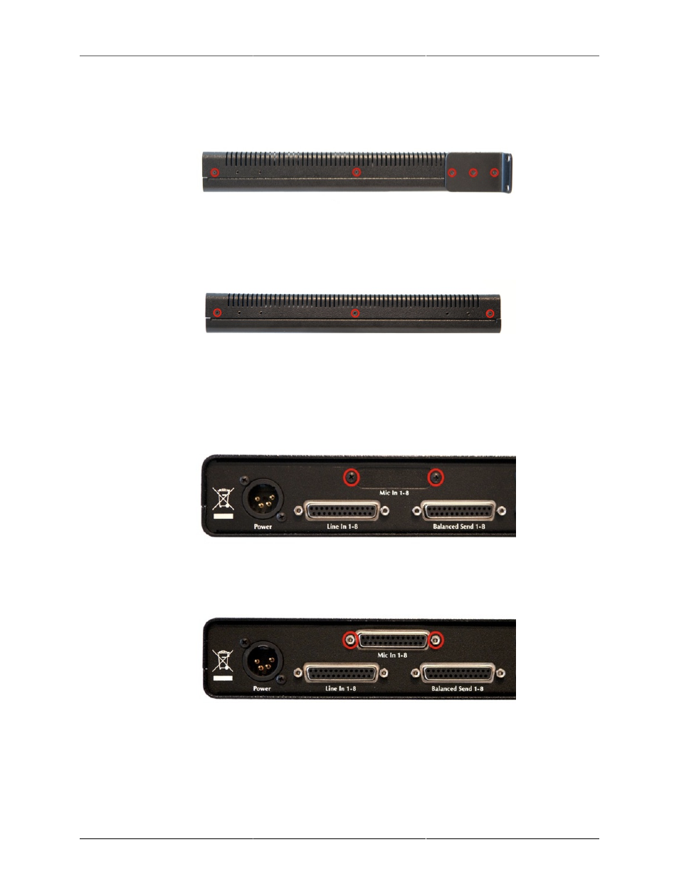
2. Remove the screws from the left and right sides of the case. If the rack ears are fitted, there will be five
screws per side. Please note that the screws on the rack ears are longer than the others. Be sure to put
the longer screws back in the rack ears when you reassemble the LIO-8.
Figure I.8: Side Screw Placement, with Rack Ear
If the rack ears are not fitted, there will be three screws per side.
Figure I.9: Side Screw Placement, No Rack Ear
Remove the top cover, and rotate the unit so that the rear panel is facing you. If you are installing the
Ch. 5-8 kit only, jump to step 9.
3. Remove the two screws holding the Mic In cover plate, then remove the plate from inside the LIO-8.
Figure I.10: Mic In Blank Plate
4. Put the DB25 connector board into the LIO-8 so that the connector comes through the hole that you just
uncovered. Put the two 7/16” standoffs through the rear panel and screw them into the DB25 connector.
Figure I.11: DB25 Connector Board Fitted
5. Use a Phillips head screw to secure the connector board to the standoff below it and put a dab of
silicone caulk on the screw to hold it in place. Next, make sure that connector J5 is bent out at a slight
angle; this is to ensure that the phantom power cable will clear the top cover.