Analog audio connections, Telescoping shield cable for instruments – Metric Halo Mobile I/O User Manual
Page 61
2882 Users Guide
61
There are six classes of connections you can make to the 2882 hardware:
1. Analog Audio
2. Copper-based Digital Audio
3. Optical-based Digital Audio
4. Clock Sync
5. FireWire
6. Power
Analog Audio Connections
The analog I/O connections on the Mobile I/O have been engineered for maximum flexibility in that they
support both balanced and unbalanced connections with a wide range of input and output levels and a wide
range of matching impedances. This means that Mobile I/O handles sources from mic level to line level and
from mic impedance to guitar impedance. With that in mind, there are a number of aspects of the design that
you should take into account when interfacing with Mobile I/O.
Whenever possible, use balanced interconnects with Mobile I/O. The performance of balanced interconnects
is much higher and much more resistant to noise interference and electrical (power) wiring problems. The
expense of balanced interconnects is not substantially higher than unbalanced connections, so if the gear that
you are interfacing with supports balanced connection — use it. If you cannot utilize balanced interconnects,
there are connection schemes that you can use that will maximize performance.
On input, at line level, it is sufficient to simply use standard unbalanced (TS) connections. If you are interfacing
with the Mobile I/O XLR inputs, you will need to ensure that pin 3 is grounded in the unbalanced adapter
cable. More information about adjusting the input level can be found in the MIO Console software chapter.
The Mobile I/O XLR inputs are all wired pin 2 hot and the 1/4” inputs are wired Tip hot.
TIP:
To use the 2882 TRS input with guitar or bass, you can simply use a standard TS guitar cable (patch
cord) and it will work fine. However, you can take advantage of the balanced input design of the 2882
to get more noise rejection than you thought possible on a guitar input.
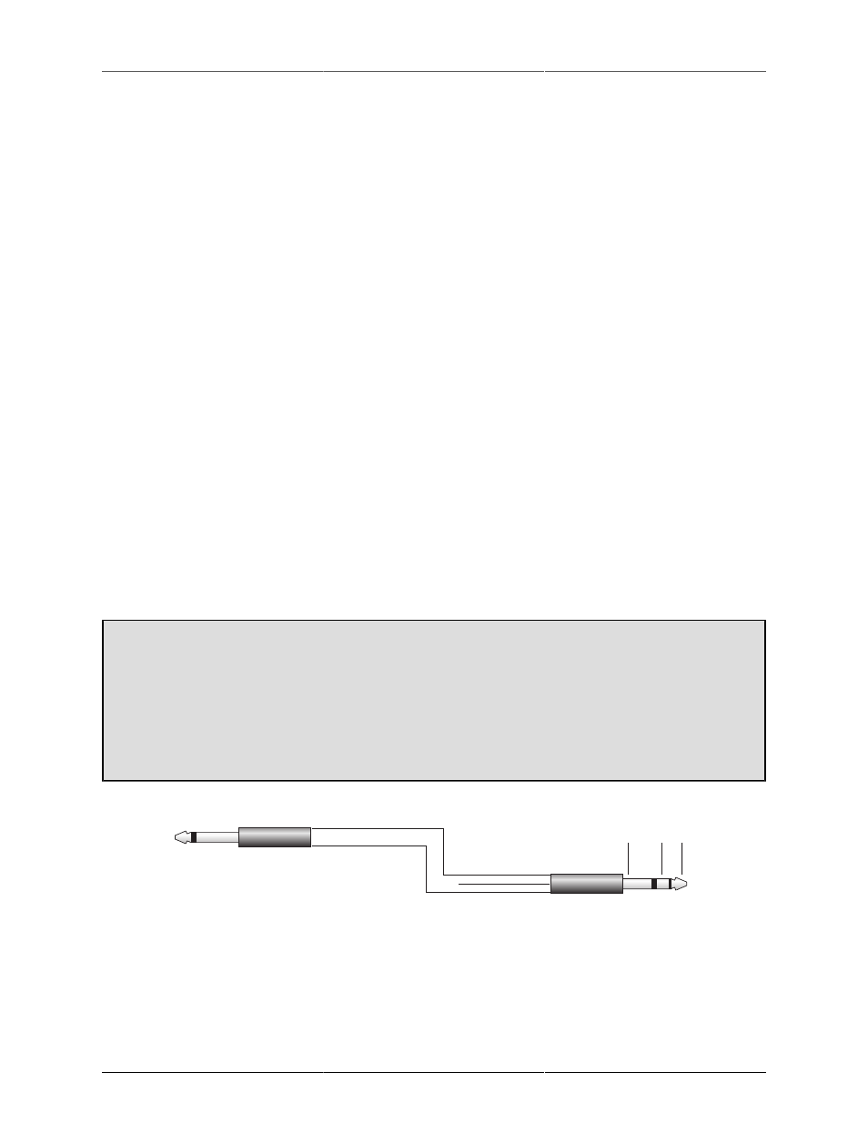
In order to do this, you will need to make a pseudo-balanced telescoping shield guitar cable. This can
be constructed with a TRS connector, a TS connector and balanced microphone cable. This cable will
treat the guitar as a floating balanced source and provide a telescoping shield from the 2882 ground.
Sleeve (Shield)
Tip (Hot)
Ring (Cold)
Tip
Sleeve
Instrument
Mobile I/O
Sleeve Ring Tip
Figure 5.12: Telescoping Shield Cable for Instruments
If you want to use the TRS inputs with balanced microphones, you will need an XLR female to 1/4” TRS bal-
anced plug adapter cable. These are available commercially, or you can construct one easily. The connections
are Tip to Pin 2, Ring to Pin 3 and Sleeve to Pin 1: