D.i. board, Line input grounding, 342 line input grounding – Metric Halo Mobile I/O User Manual
Page 342: H.4. d.i. board jumper sites, 342 h.5. shield lift jumper sites, H.1. d.i. board gain settings
ULN-8/LIO-8 Jumper Settings
342
D.I. Board
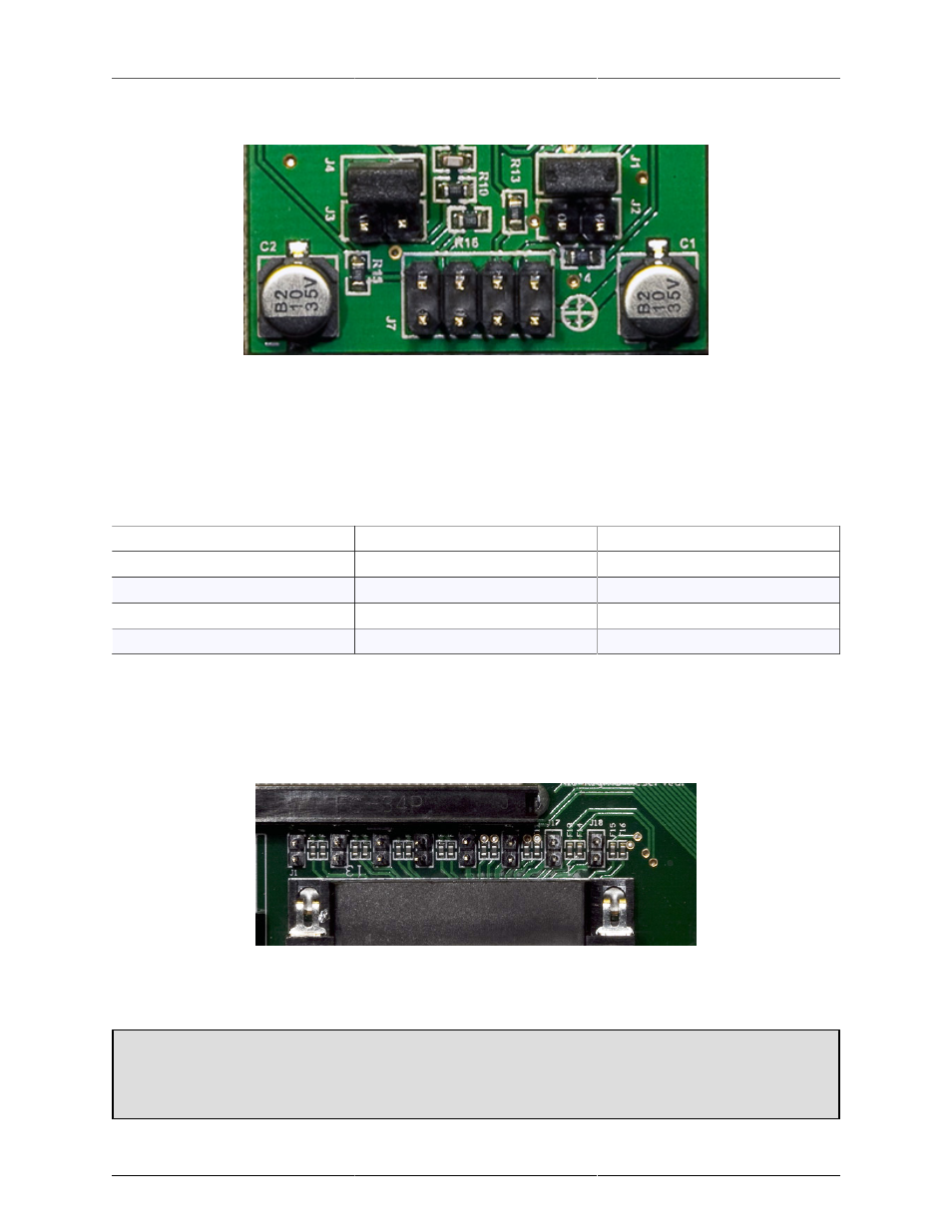
Figure H.4: D.I. Board Jumper Sites
There are 4 pairs of pin headers on the DI board mounted to the front panel, two pair per channel. The pair
of pins closest to the TRS connectors (for each channel) is the low gain set. The pair closest to the ribbon
cable is the high gain set.
When installing a jumper, it should be within the white box next to the jumper label, not connecting adjacent
jumpers.
Table H.1. D.I. board gain settings
Gain
Channel 1
Channel 2
0.0 dB
None
None
10 dB
J4
J1
17.85 dB
J3
J2
20 dB
J3 and J4
J1 and J2
Line input grounding
The shield on the line inputs can be lifted on a per-channel basis. These jumpers can be accessed directly on
the LIO-8; to access them on the ULN-8 (or LIO-8 with mic pres) you must remove the mic pre(s) and connector
board. These jumpers are located on the connector board at the rear of the interface, directly behind the Line
input connector. The channels start with input 1 on J1 and go the the right, ending with channel 8 on J18.
Figure H.5: Shield Lift Jumper Sites
By removing the jumpers, you disconnect the shield from the connected input. Having the jumper installed
connects the shield to the ground of the interface.
Connecting unbalanced sources
It has been our experience that it is best to have the ground jumpers installed when connecting unbal-
anced sources to the line inputs.