Conclusion, Connecting a three box system – Metric Halo Mobile I/O User Manual
Page 231
Routing Examples
231
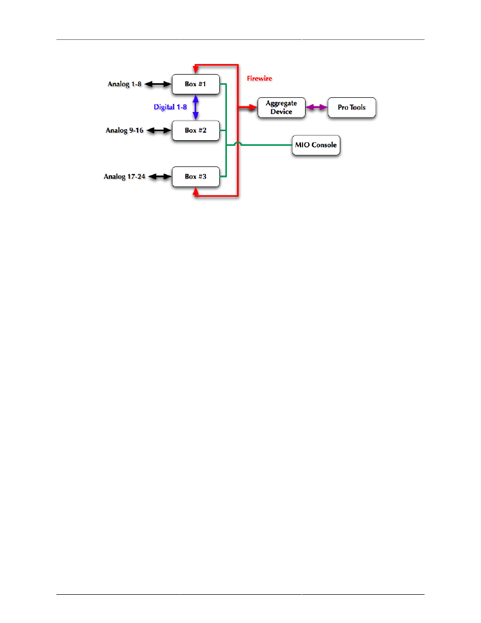
Figure 13.47: Connecting a Three Box System
• Analog I/O 1-8 are on box #1, which is the first box of an aggregate. These should appear as FW 1-8
in the aggregate.
• Analog I/O 9-16 are on box #2; this is connected to box #1 over AES and is not part of the aggregate.
In box #1, the AES channels would be sent to FW 9-16 via the direct outs.
• Analog I/O 17-24 are on box #3, which is the second box of an aggregate. These should appear as FW
21-29 in the aggregate.
Conclusion
The preceding examples should give you a sense of the possibilities that are enabled by the routing and mixing
features of Mobile I/O. While this is just a starting point, we have covered all of the basic operations required
to manipulate Mobile I/O with complex routing. You should be able to build upon these scenarios to construct
routings that suit your needs and your workflow.