Yaskawa AC Drive Z1000 User Manual
Page 169
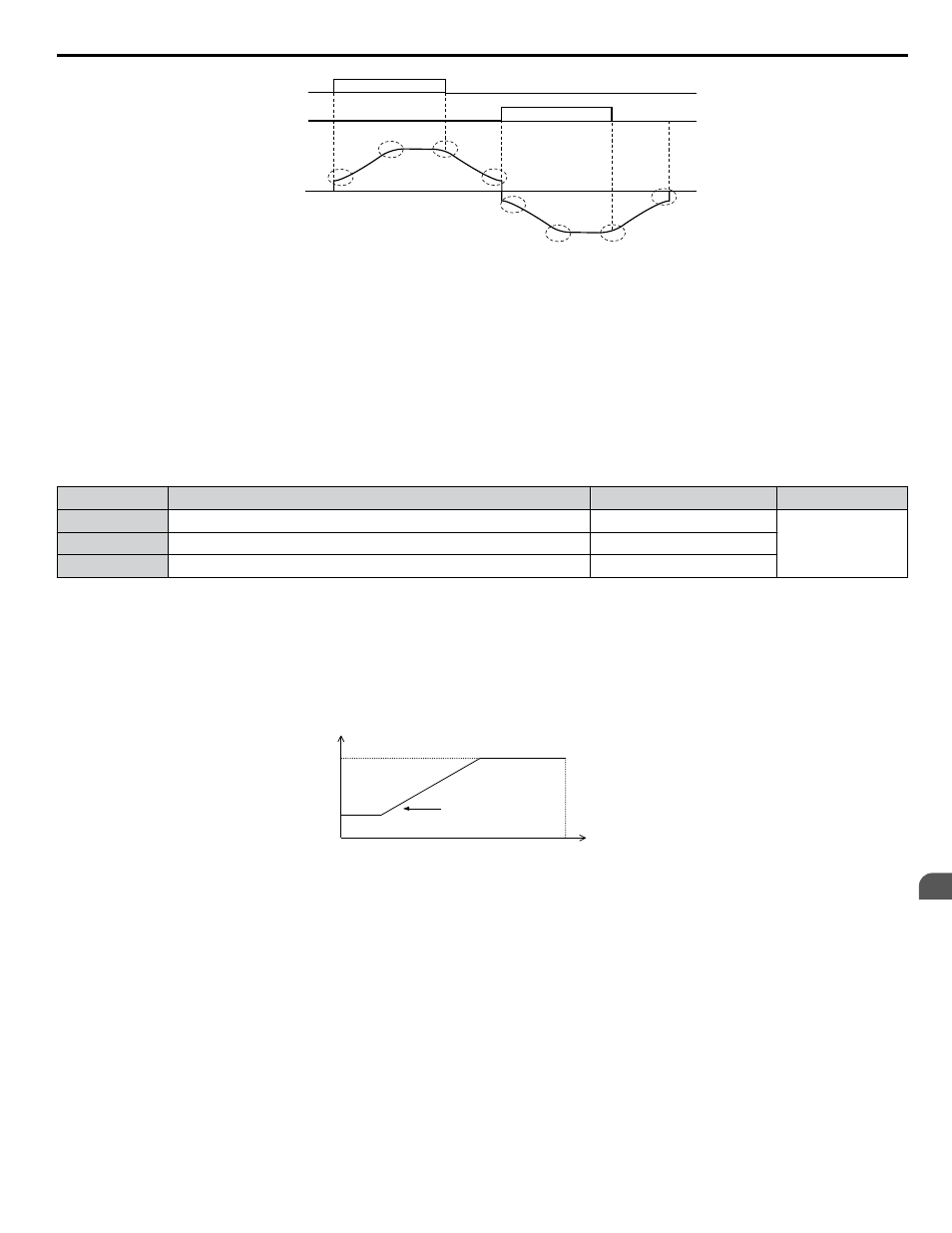
C2-02
C2-01
0.20 s
<1>
0.20 s
<1>
C2-02
C2-01
0.20 s
<1>
0.20 s
<1>
FWD run
REV run
Output
frequency
<1> S-Curve characteristic at Decel Start/End is fixed to 0.20 s.
Figure 4.30 S-Curve Timing Diagram - FWD/REV Operation
Setting the S-curve will increase the acceleration and deceleration times.
Actual accel time = accel time setting + (C2-01 + C2-02) / 2
n
C6-03, C6-04, C6-05: Carrier Frequency Upper Limit, Lower Limit, Proportional Gain
Note:
C6-04 and C6-05 are available in V/f Control mode only.
These parameters set a user-defined or a variable carrier frequency. Set C6-02 to F to set the upper and lower limits and the
carrier frequency proportional gain.
No.
Parameter Name
Setting Range
Default
C6-03
Carrier Frequency Upper Limit
1.0 to 15.0 kHz
Determined by
C6-02
C6-04
Carrier Frequency Lower Limit (V/f Control only)
1.0 to 15.0 kHz
C6-05
Carrier Frequency Proportional Gain (V/f Control only)
0 to 99
Setting a Fixed User-Defined Carrier Frequency
A carrier frequency between the fixed selectable values can be entered in parameter C6-03 when C6-02 is set to F.
In V/f Control, adjust parameter C6-04 to the same value as C6-03.
Setting a Variable Carrier Frequency (V/f Control)
In V/f Control, the carrier frequency can be set up to change linearly with the output frequency by setting the upper and lower
limits for the carrier frequency and the carrier frequency proportional gain (C6-03, C6-04, C6-05) as shown in
C6-03
C6-04
E1-04
x C6-05
Output Frequency
Output
Frequency
Max Output Frequency
Carrier Frequency
Figure 4.31 Carrier Frequency Changes Relative to Output Frequency
Note:
When C6-05 is set lower than 7, C6-04 is disabled and the carrier frequency will be fixed to the value set in C6-03.
n
d1-01 to d1-04, d1-16, and d1-17: Frequency References 1 to 4, 16, and Jog Frequency
Reference
The drive lets the user switch between up to 5 preset frequency references during run (including the Jog reference) through
the digital input terminals. The drive uses the acceleration and deceleration times that have been selected when switching
between each frequency reference.
The Jog frequency overrides all other frequency references and must be selected by a separate digital input.
The multi-speed references 1 and 2 can be provided by analog inputs.
4.13 Advanced Drive Setup Adjustments
YASKAWA ELECTRIC TOEP C710616 45E YASKAWA AC Drive – Z1000 User Manual
169
4
Start-Up Programming & Operation