Yaskawa AC Drive Z1000 User Manual
Page 87
n
Cable Length Between Drive and Motor
Voltage drop along the motor cable may cause reduced motor torque when the wiring between the drive and the motor is too
long, especially at low frequency output. This can also be a problem when motors are connected in parallel with a fairly long
motor cable. Drive output current will increase as the leakage current from the cable increases. An increase in leakage current
may trigger an overcurrent situation and weaken the accuracy of the current detection.
Adjust the drive carrier frequency according to
. If the motor wiring distance exceeds 100 m because of the system
configuration, reduce the ground currents.
Refer to C6-02: Carrier Frequency Selection on page 133
.
Table 3.4 Cable Length Between Drive and Motor
Cable Length
50 m or less
100 m or less
Greater than 100 m
Carrier Frequency
12.5 kHz or less
5 kHz or less
2 kHz or less
Note:
1. When setting carrier frequency for drives running multiple motors, calculate cable length as the total wiring distance to all connected
motors.
2. The maximum cable length when using OLV/PM (A1-02 = 5) is 100 m.
3. Do not use a long distance shielded line if there is an overvoltage problem at start. Either lower the carrier frequency or switch on the
internal EMC filter if the power supply has a neutral ground.
n
Ground Wiring
Follow the precautions below when wiring the ground for one drive or a series of drives.
DANGER! Electrical Shock Hazard. Do not touch SW1 or SW2 screws while power is applied to the drive. Failure to comply will result in
death or serious injury.
WARNING! Electrical Shock Hazard. Make sure the protective earthing conductor complies with technical standards and local safety
regulations. Because the leakage current exceeds 3.5 mA, IEC/EN 61800-5-1 states that either the power supply must be automatically
disconnected in case of discontinuity of the protective earthing conductor or a protective earthing conductor with a cross-section of at least
10 mm
2
(Cu) or 16 mm
2
(Al) must be used. Failure to comply may result in death or serious injury.
WARNING! Electrical Shock Hazard. Always use a ground wire that complies with technical standards on electrical equipment and minimize
the length of the ground wire. Improper equipment grounding may cause dangerous electrical potentials on equipment chassis, which could
result in death or serious injury.
WARNING! Electrical Shock Hazard. Be sure to ground the drive ground terminal (200 V class: ground to 100 Ω or less and 400 V class:
ground to 10 Ω or less). Improper equipment grounding could result in death or serious injury by contacting ungrounded electrical equipment.
NOTICE: Do not share the ground wire with other devices such as welding machines or large-current electrical equipment. Improper
equipment grounding could result in drive or equipment malfunction due to electrical interference.
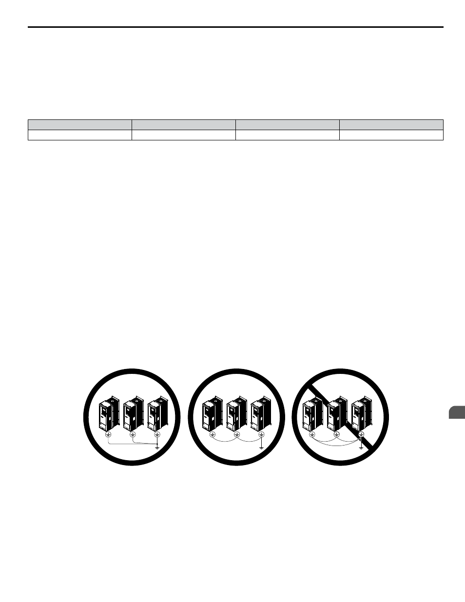
NOTICE: When using more than one drive, ground multiple drives according to instructions. Improper equipment grounding could result in
abnormal operation of drive or equipment.
when using multiple drives. Do not loop the ground wire.
Figure 3.31 Ground Wiring for Multiple Drives
3.8 Main Circuit Wiring
YASKAWA ELECTRIC TOEP C710616 45E YASKAWA AC Drive – Z1000 User Manual
87
3
Electrical Installation