Wiring the control circuit terminal, For details on wiring – Yaskawa AC Drive Z1000 User Manual
Page 95
u
Wiring the Control Circuit Terminal
This section describes the proper procedures and preparations for wiring the control terminals.
WARNING! Electrical Shock Hazard. Do not remove covers or touch the circuit boards while the power is on. Failure to comply could result
in death or serious injury.
NOTICE: Separate control circuit wiring from main circuit wiring (terminals R/L1, S/L2, T/L3, -M, +M, -, +1, +3, U/T1, V/T2, W/T3) and other
high-power lines. Improper wiring practices could result in drive malfunction due to electrical interference.
NOTICE: Separate wiring for digital output terminals MA, MB, MC, and M1 to M6 from wiring to other control circuit lines. Improper wiring
practices could result in drive or equipment malfunction or nuisance trips.
NOTICE: Use a class 2 power supply when connecting to the control terminals. Improper application of peripheral devices could result in
drive performance degradation due to improper power supply. Refer to NEC Article 725 Class 1, Class 2, and Class 3 Remote-Control,
Signaling, and Power Limited Circuits for requirements concerning class 2 power supplies.
NOTICE: Insulate shields with tape or shrink tubing to prevent contact with other signal lines and equipment. Improper wiring practices could
result in drive or equipment malfunction due to short circuit.
NOTICE: Connect the shield of shielded cable to the appropriate ground terminal. Improper equipment grounding could result in drive or
equipment malfunction or nuisance trips.
Terminal Wiring Guide on page 95
for details. Prepare the ends of the control circuit wiring as shown in
.
Refer to Wire Gauges on page 93
NOTICE: Do not tighten screws beyond the specified tightening torque. Failure to comply may result in erroneous operation, damage to the
terminal block, or cause a fire.
NOTICE: Use shielded twisted-pair cables as indicated to prevent operating faults. Improper wiring practices could result in drive or
equipment malfunction due to electrical interference.
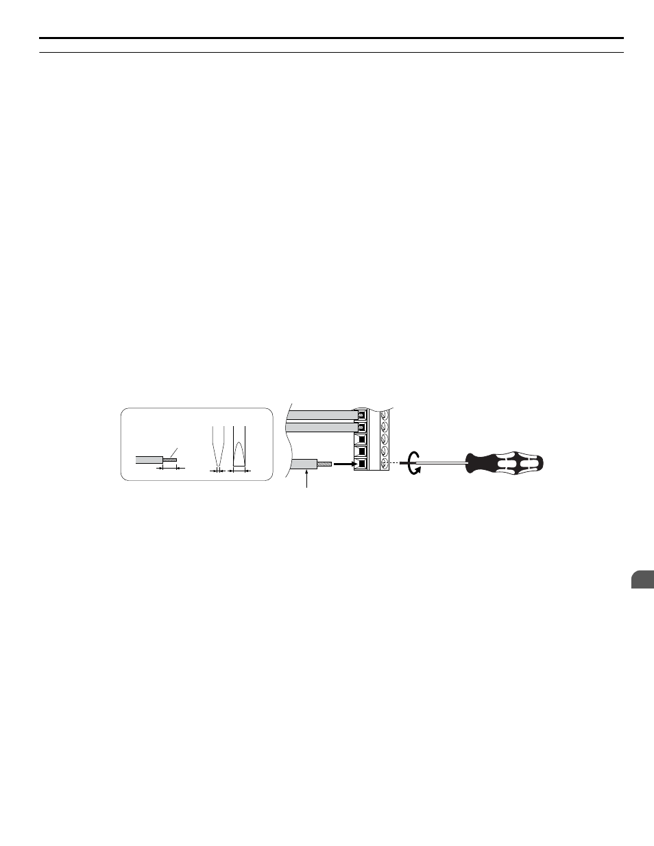
Connect control wires as shown in
and
Yaskawa recommends Phoenix Contact screwdriver model SZF 0-0.4 x 2.5 or equivalent to wire the terminal block.
A
B
C
D
Preparing wire
terminal ends
0.4
2.5
A – Loosen screw to insert wire.
B – Single wire or stranded wire
C – Avoid fraying wire strands when
stripping insulation from wire. Strip
length 5.5 mm.
D – Blade depth of 0.4 mm or less
Blade width of 2.5 mm or less
Figure 3.40 Terminal Wiring Guide
Use the cable tie holes and cable hooks when wiring control terminals.
Note:
Take proper precautions when wiring the cables so that the front covers will easily fit back onto the drive. Make sure cables are not pinched
between the front covers and the drive when replacing the covers.
3.9 Control Circuit Wiring
YASKAWA ELECTRIC TOEP C710616 45E YASKAWA AC Drive – Z1000 User Manual
95
3
Electrical Installation