3 main circuit connection diagram, Pulse/18-pulse rectification, Three-phase 200 v class (2a0011 to 2a0273) – Yaskawa AC Drive Z1000 User Manual
Page 65: Three-phase 400 v class (4a0005 to 4a0302), Three-phase 200 v class (2a0343 and 2a0396), Three-phase 400 v class (4a0361 to 4a0590), Main circuit connection diagram
3.3 Main Circuit Connection Diagram
Refer to diagrams in this section when wiring the main circuit of the drive. Connections may vary based on drive capacity.
The DC power supply for the main circuit also provides power to the control circuit.
u
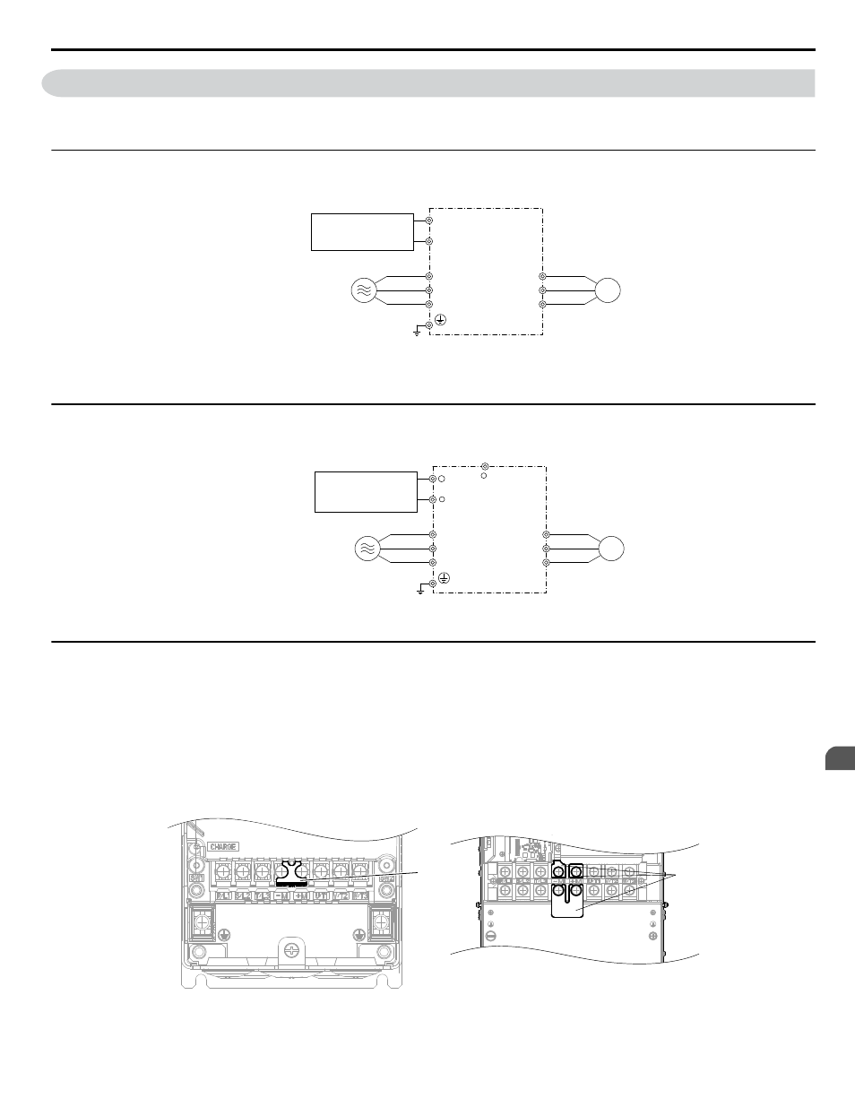
Three-Phase 200 V Class (2A0011 to 2A0273)
Three-Phase 400 V Class (4A0005 to 4A0302)
Drive
Motor
+M
R/L1
S/L2
T/L3
U/T1
V/T2
W/T3
-M
3-Phase power supply
200 to 240 Vac, 50 to 60 Hz
380 to 480 Vac, 50 to 60 Hz
12-Pulse/18-Pulse
Rectification (Option) <1>
<1> +M and -M are for rectification options only. Do not use for dynamic braking or line-regeneration.
Figure 3.2 Connecting Main Circuit Terminals
u
Three-Phase 200 V Class (2A0343 and 2A0396)
Three-Phase 400 V Class (4A0361 to 4A0590)
12-Pulse/18-Pulse
Rectification (Option) or
DC power power supply
+3
R/L1
S/L2
T/L3
U/T1
V/T2
W/T3
Drive
Motor
−
3 Phase power supply
200 to 240 Vac, 50 to 60 Hz
380 to 480 Vac, 50 to 60 Hz
+ 1
Figure 3.3 Connecting Main Circuit Terminals
u
12-Pulse/18-Pulse Rectification
Operation with 12-pulse/18-pulse rectification requires the user to separately prepare a 3-winding/4-winding transformer for
the power supply. Contact Yaskawa or your nearest sales representative for the transformer specifications.
n
Wiring to –M/+M Terminals (2A0011 to 2A0273 and 4A0005 to 4A0302)
Access the –M/+M terminals by cutting off the protection cover on models 2A0011 to 2A0114 and 4A0005 to 4A0096 or by
removing the protection sheet on –M/+M terminals on models 2A0143 to 2A0273 and 4A0124 to 4A0302.
–M/+M are for rectification options only. Do not use for dynamic braking or line-regeneration.
A
A
A –Protective covering over –M/+M terminals
Figure 3.4 –M/+M Terminals
3.3 Main Circuit Connection Diagram
YASKAWA ELECTRIC TOEP C710616 45E YASKAWA AC Drive – Z1000 User Manual
65
3
Electrical Installation