E1-03: v/f pattern selection, 13 advanced drive setup adjustments – Yaskawa AC Drive Z1000 User Manual
Page 171
n
d3-01 to d3-04: Jump Frequencies 1, 2, 3 and Jump Frequency Width
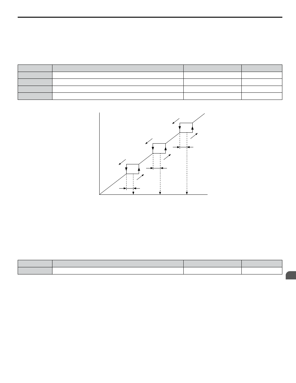
The Jump frequencies are frequency ranges at which the drive will not operate. The drive can be programmed with three
separate Jump frequencies to avoid operating at speeds that cause resonance in driven machinery. If the speed reference falls
within a Jump frequency dead band, the drive will clamp the frequency reference just below the dead band and only accelerate
past it when the frequency reference rises above the upper end of the dead band.
Setting parameters d3-01 through d3-03 to 0.0 Hz disables the Jump frequency function.
No.
Parameter Name
Setting Range
Default
d3-01
Jump Frequency 1
0.0 to 240.0 Hz
0.0 Hz
d3-02
Jump Frequency 2
0.0 to 240.0 Hz
0.0 Hz
d3-03
Jump Frequency 3
0.0 to 240.0 Hz
0.0 Hz
d3-04
Jump Frequency Width
0.0 to 20.0 Hz
1.0 Hz
shows the relationship between the Jump frequency and the output frequency.
Frequency
Reference
Output
Frequency
Jump
Frequency
Width (d3-04)
Jump
Frequency 3
d3-03
Jump
Frequency 2
d3-02
Jump
Frequency 1
d3-01
Frequency
reference
decreases
Frequency
reference
increases
Jump
Frequency
Width (d3-04)
Jump
Frequency
Width (d3-04)
Figure 4.33 Jump Frequency Operation
Note:
1. The drive will use the active accel/decel time to pass through the specified dead band range, but will not allow continuous operation in
that range.
2. When setting more than one Jump frequency, make sure that d3-01≥ d3-02 ≥ d3-03.
n
E1-03: V/f Pattern Selection
Selects the V/f pattern for the drive and motor from 15 predefined patterns or creates a custom V/f pattern.
No.
Parameter Name
Setting Range
Default
E1-03
V/f Pattern Selection
0 to F
<1>
F
<2>
<1> Settings 0 through E are not available in OLV/PM (A1-02 = 5).
<2> Parameter is not reset to the default value when the drive is initialized using A1-03.
Setting a Predefined V/f Pattern (Setting 0 to F)
Choose the V/f pattern that best meets the application demands from the table below. These settings are available only in
V/f Control modes. Set the correct value to E1-03. Parameters E1-04 to E1-13 can only be monitored, not changed.
Note:
1. Setting an improper V/f pattern may result in low motor torque or increased current due to overexcitation.
2. Drive initialization does not reset parameter E1-03.
4.13 Advanced Drive Setup Adjustments
YASKAWA ELECTRIC TOEP C710616 45E YASKAWA AC Drive – Z1000 User Manual
171
4
Start-Up Programming & Operation