Rear panel – ATEIS IDA8 User Manual
Page 305
Product Features
305
© 2012 ATEÏS
4.3.1.3
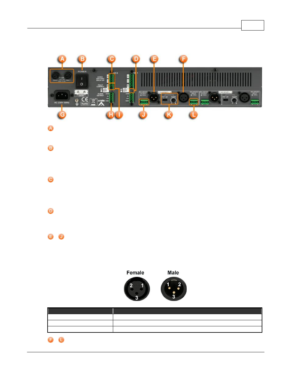
Rear Panel
Fuse Receptacles:
Two fuse receptacles are located on the left of the amplifier’s rear panel.
Power Switch:
The power switch is a two position switch. Pushing up the power switch ( I position) will power on
the device, pushing it down (O position) will off the power. When the power switch is on the I
position, the front panel power LED will light up.
Channel 1/2 24VDC battery backup connector:
The SPA amplifier can be operated with battery backup. Use the channel 1 and channel 2 "24VDC
Battery Backup" connector to do so. This 24VDC power supply can be used when no AC power is
available. When in use, the front panel Power LED will be lit as well as the front panel DC LED.
Fault LED On/Off:
Enables/Disables the Fault Power LED indicator. In need of turning off the indicator, use a thin
screwdriver to press the retractable button.
&
Channel 1/2 Outputs:
Each channel outputs a replica of the corresponding balanced audio input signal either on the XLR
connector or on the Euro-terminal block.
The following table lists the pins of XLR connector (both Female and Male):
Item
Description
Pin1
Chassis ground (cable shield).
Pin2
Positive polarity terminal for balanced audio circuits (aka "hot").
Pin3
Negative polarity terminal for balanced circuits (aka "cold").
&
Channel 1/2 Inputs: