ATEIS IDA8 User Manual
Page 83
Product Features
83
© 2012 ATEÏS
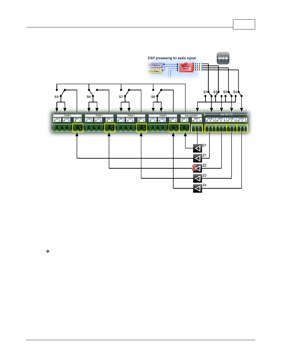
amplifier can serve Zone 1 to Zone 4. The figure below shows this concept:
Share the Backup Am plifier
In the above figure, Z1~Z4 represents the normal amplifier for Z1~Z4. B1 is the backup amplifier.
S1~S4 are switches used to select the path of the audio signal coming from the DSP processor.
S5~S8 switches are used to select the path going to the Line A/B output. B1 can service Zone1 to
Zone 4 by controlling switches S1~S8. In this example, amplifier Z2 has failed. The IDA8 controls S6
and S2 to change the audio path from the normal amplifier (Z2) to the backup amplifier (B1). The
behavior of the other channels are the same as Channel 2. A backup amplifier cannot serve more
than one zone at the same time. In such limitation, for example, if amplifier Z3 fails, then there is no
available amplifier for backup.
Advance Backup Amplifier Setup:
There are more cost effective solutions of the IDA8 backup amplifier setup. It is possible to let one
backup amplifier serve more than four zones. See the figure below. An Ateis Net system consists of
one IDA8C and two IDA8S's. There are 24 zones in the system divided into three backup amplifier
groups. For each group, there is a backup amplifier which becomes redundant if any of the normal
amplifiers in the group fail. To group zones, you need to wire AMP I and AMP O between the backup
amplifier connectors. Red lines show the wire connections to group zones.