Ssi analog input setup, Ssi configuration and calibration – Super Systems PC Configurator 2 User Manual
Page 173
Super Systems Inc.
Page 173 of 201
Configurator Manual #4562 Rev D
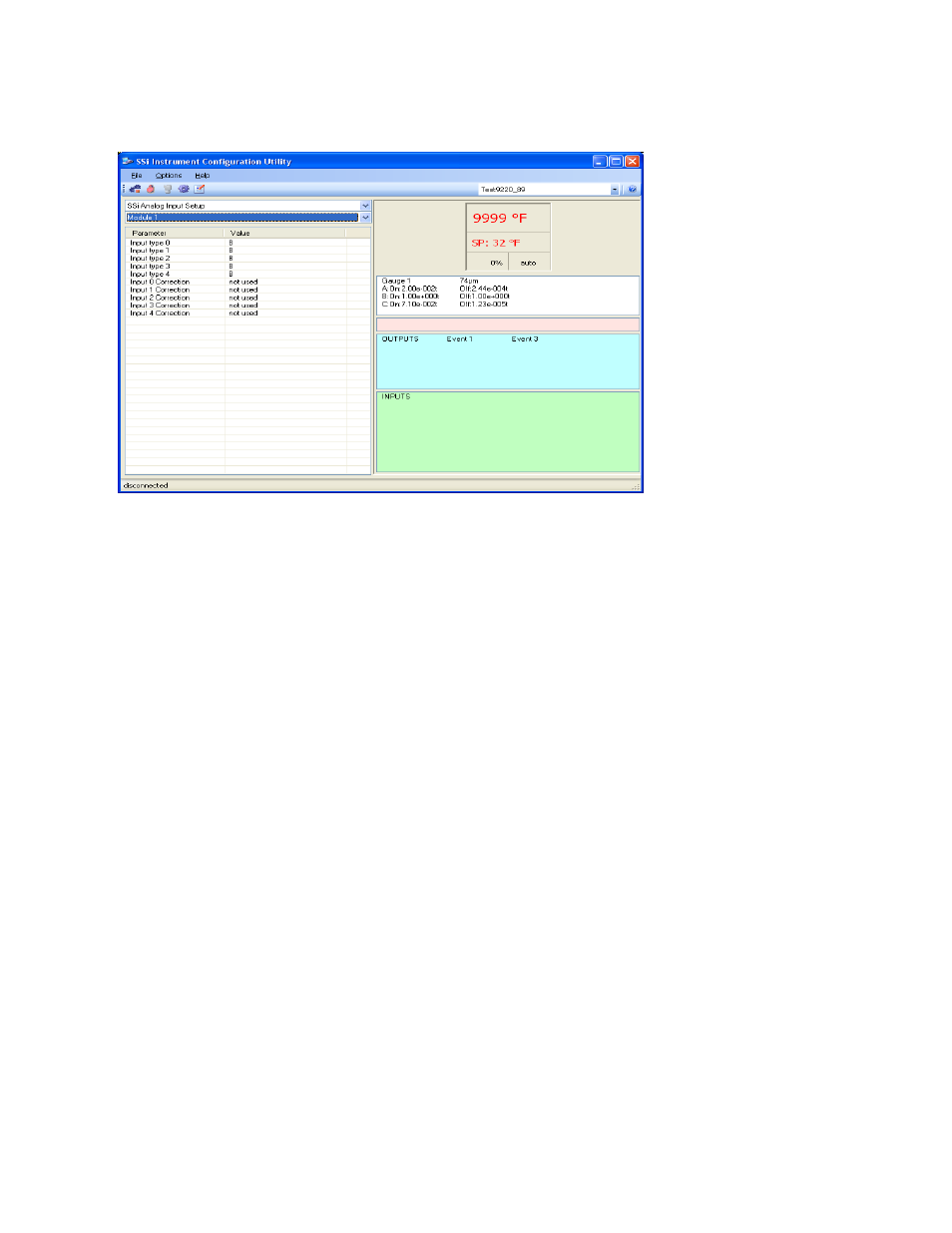
SSi Analog Input Setup
The SSi Analog Input
Setup menu option
allows the user an input
selection of five inputs
per module and five
input corrections per
module. There are
eight modules available.
It is configurable for
voltage of T/C
(universal input), and it
is typically used for
Load T/Cs and Auxiliary
Flow Meters. Clicking
on any of the values
will display an input box
from which the user
can select the input type from a drop-down list with the following values:
B NNM
160
mV
C R
80
mV
E
S
40 mV
J
T
20 mV
K 2.5
volts 4-20
mA/124
Ω
N
1.25
volts
4-20
mA/62
Ω
The options for the input corrections are: not used, Curve 1 – Curve 3.
SSi Configuration and Calibration
*** This menu option is the same as the
SSi Configuration and Calibration
menu option under
the
Configurator-9200 Drop Down Menu
. ***
The list of screens from the User Calibration section and the Full Calibration section is listed
below in sequential order. Screen only found in the Full Calibration section are displayed in
Italics
. Screens only found in the User Calibration section are displayed in Bold.
1. Cold Junction
2.
Zero/Span Input 0/Range 0
3.
Zero/Span Input 0/Range 1
4.
Zero/Span Input 0/Range 2
5.
Zero/Span Input 0/Range 3
6.
Zero/Span Input 1/Range 0
7.
Zero/Span Input 1/Range 1
8.
Zero/Span Input 1/Range 2
9. Zero/Span Input 1/Range 3
10.
Zero/Span Input 2/Range 0
11. Zero/Span Input 2/Range 1
12.
Zero/Span Input 2/Range 2
13.
Zero/Span Input 2/Range 3