Calibration – Super Systems PC Configurator 2 User Manual
Page 45
Super Systems Inc.
Page 45 of 201
Configurator Manual #4562 Rev D
Calibration
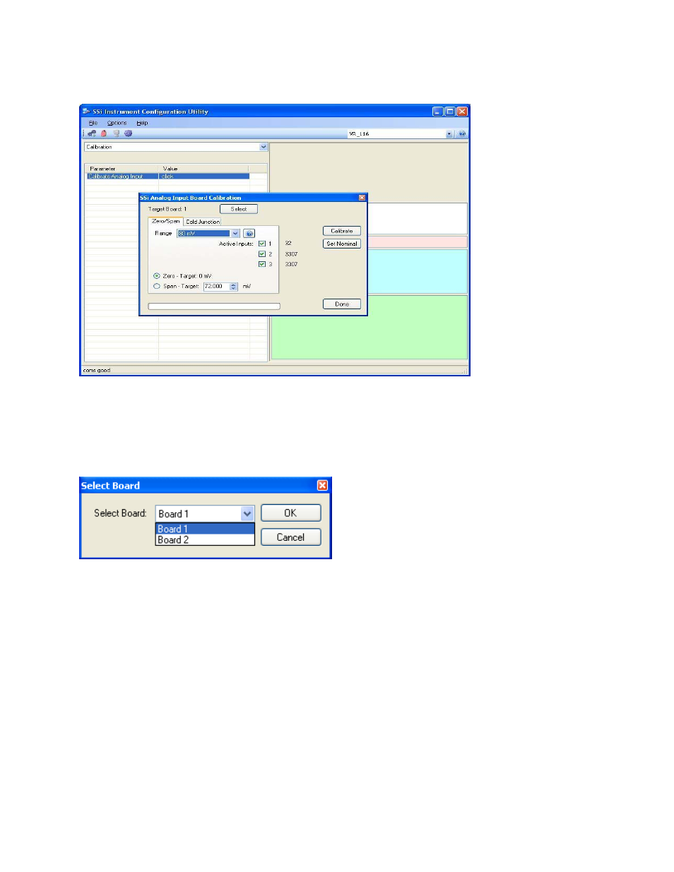
Configurator – 8500 Calibration Menu Option
The Calibration menu screen will allow the user to calibration the zero, span, and cold junction
trim value for all of the inputs on each board.
The Select button will allow the user to select one of the current boards to perform a
calibration on.
Configurator – Board Selector
Select the appropriate board and click on the OK button. Clicking on the Cancel button will
not select the board to calibrate.
Note: A board must be selected for calibration to begin
.
The user will need a thermocouple calibrator capable of outputting a thermocouple signal to
calibrate the zero, span or cold junction value of the video recorder data logger. The user will
need to connect the calibrator to one of the inputs on the data logger for the channel that will
be calibrated. It is recommended to let everything (calibrator and datalogger) sit for
approximately thirty minutes to allow the temperature to achieve equilibrium. Set up the
calibrator for the specific thermocouple type of the thermocouples in the video recorder
datalogger, i.e. type K, type J, etc. Then, source a specific temperature, like 1000
°F, or
millivolt to the connected input. It is recommended that the actual temperature used be similar
to an appropriate process temperature. For example, if your equipment normally operates at
1700
°F, then perform the cold junction calibration using a 1700 °F signal. It is important to
note that when performing a zero or span calibration,
do not use
regular thermocouple wiring.
Instead, use any kind of regular sensor wire, or even regular copper wire. To perform the