Super Systems PC Configurator 2 User Manual
Page 60
Super Systems Inc.
Page 60 of 201
Configurator Manual #4562 Rev D
The “PV” Instrument Register box will allow the user to set the physical instrument register for
the process variable. The “SP” Instrument Register box will allow the user to set the physical
instrument register for the set point. The “Output” Instrument Register box will allow the user
to set the physical instrument register for the output. These registers will be the actual
registers in the slave instrument where the data is located. The range for all of the Instrument
Register boxes is 0 to 100,000.
The “PV” Input Scale box will allow the user to set the input scaling for the process variable.
The “SP” Input Scale box will allow the user to set the input scaling for the set point. The
“Output” Input Scale box will allow the user to set the input scaling for the output. This value
will be used as a divider when any value is read in. For example, if the scaling is set to 10, and
a 5005 if read in, the value will be treated as 500.5. The range for all of the Input Scale boxes
is 1 to 100.
The “PV” Output Scale box will allow the user to set the output scaling for the process variable.
The “SP” Output Scale box will allow the user to set the output scaling for the set point. The
“Output” Output Scale box will allow the user to set the output scaling for the output. This
value will be used as a multiplier if any value needs to be written somewhere. For example, if
the scaling is set to 10, and a value of 510 needs to be sent, the value that will be sent will be
5100. The range for all of the Output Scale boxes is 1 to 100.
The Apply button will set any changes made in the “Communications and Mapping Table”
section.
Block Write Table Section
This section of the form allows the user to set up the write block for an instrument. This will
allow the user to write data to a specific instrument. The drop-down list will allow the user to
select which write block to set up. The options are: Write 1 – Write 5.
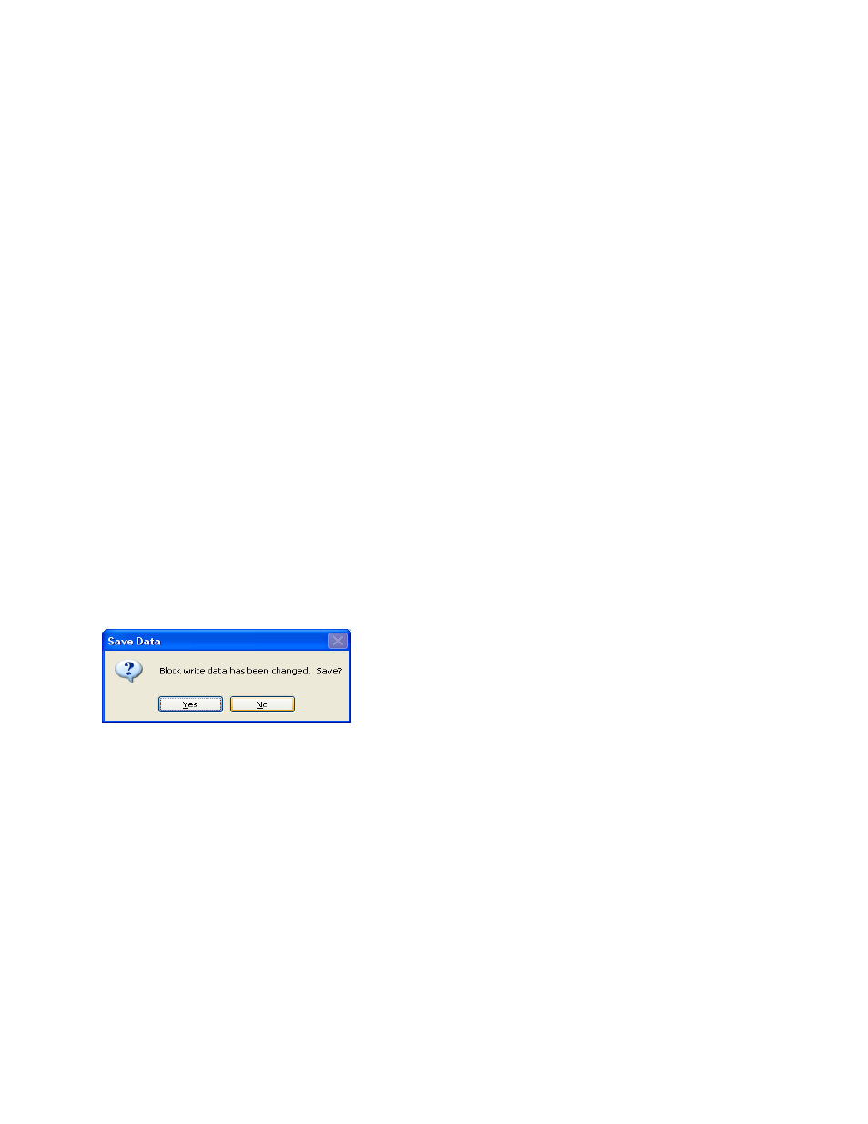
Note: If any changes
have been made to the current write block, the user will have the option to save the changes
before the new write block is selected
.
Configurator – Confirm Save Changes to Block Write
Clicking on the Yes button will save the changes and select the new write block. Clicking on
the No button will not save any changes and it will select the new write block.
The “Instrument Number” box will allow the user to select the instrument to write to. This will
select the specific slave instrument to write to. The slave instruments can be set up on the
Slave Instrument Setup
menu option. See the section
Slave Instrument Setup
for more
information on setting up a slave instrument. The range is 0 to 32.
The “Update Interval (seconds)” box will allow the user to set the update interval in seconds for
the write. This will determine how often the slave instrument will be written to. The range is 0
to 300 seconds.
The “Data Register Offsets” box will allow the user to set up the data register offsets for the
write to read from. This will be the beginning register on the host instrument, such as a 9005
controller, to read from. The read will be as long as the value in the “Number of Words to
Send” box. The range is 0 to 999.