Super Systems PC Configurator 2 User Manual
Page 199
Super Systems Inc.
Page 199 of 201
Configurator Manual #4562 Rev D
Appendix G – Examples
Example 1 – Cascade Setup for the 9205
The 9205 can do cascade control using loops 2 and 3 and inputs 2 and 3 respectively. In
cascade control mode, the output of loop 3 sets the setpoint of loop 2. The 9205 must be in
Cascade mode in order for these settings to be applicable. To set the 9205 in Cascade mode,
select the “PVT Type” item under the
Furnace Setup
menu. “Cascade” will be on of the options
listed in the drop-down list that is displayed. Once this option is selected, there will be a few
more options displayed on the
Furnace Setup
menu screen and the
PID Loop Setup
menu
screen.
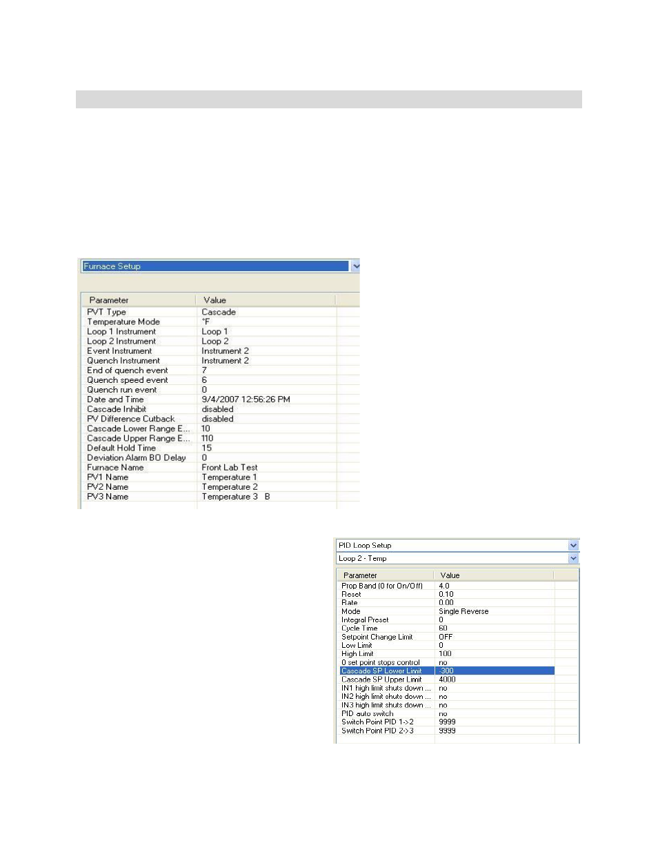
On the
Furnace Setup
menu, there will
be four more fields: Cascade Inhibit, PV
Difference Cutback, Cascade Lower
Range EOPV (End of PV Difference),
and Cascade Upper Range EOPV.
Cascade Inhibit is one option for
cascade control. The Cascade Inhibit
will be either enabled or disabled. In
normal cascade operation, the inhibit
would be disabled. When tuning loop 2,
however, it would be easier if the
cascade inhibit is enabled sot that loop
3 does change the setpoint of loop 2.
The PV Difference Cutback will be either
enabled or disabled. The purpose of
the PV Difference cutback is to keep the
PV for loop 2 from getting too far ahead
of loop 3. The Cascade Lower Range
EOPV has a range of –300 to 10000. The lower range EOPV sets the point at which the
maximum output of loop 2 begins to be
limited. The Cascade Upper Range EOPV has
a range of –300 to 10000. The upper range
EOPV defines the point at which the loop 2
output is limited to 0%. For example, if the
lower range EOPV is set to 10, the cutback
will begin when the loop 2 PV is 10 degrees
greater than the loop 3 PV. If the upper range
EOPV is set to 110, then when loop 2’s PV is
110 degrees above loop 3’s PV, the loop 2
control output is limited to 0.
On the
PID Loop Setup
menu, there will be
two more fields: Cascade SP Lower Limit, and
Cascade SP Upper Limit. The value range of
the setpoint is provided by these two setup
parameters. When loop 3’s control output is
at 0%, the cascade SP lower limit is used. When loop 3’s control output is at 100%, the