2 mrpp typical scenario 2 – Accton Technology ES4626 User Manual
Page 834
834
Switch(MRPP-ring-4000)#exit
Switch(Config)#
SWITCH D configuration Task Sequence:
Switch(Config)#MRPP enable
Switch(Config)#MRPP ring 4000
Switch(MRPP-ring-4000)#control-vlan 4000
Switch(MRPP-ring-4000)#primary-port Ethernet 1/11
Switch(MRPP-ring-4000)#secondary-port Ethernet 1/12
Switch(MRPP-ring-4000)#enable
Switch(MRPP-ring-4000)#exit
Switch(Config)#
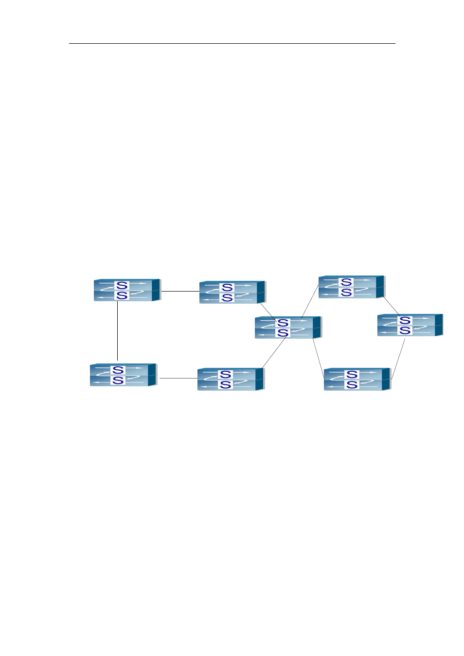
21.4.2 MRPP typical scenario 2
SWITCH A
SWITCH B
SWITCH D
SWITCH C
SWITCH E
SWITCH F
SWITCH G
SWITCH H
Master
Node
Ring 4000
Ring
100
Master Node
E1
E2
E2
E1
E2
E2
E2
E2
E2
E2
E1
E1
E1
E1
E3
E4
E1
Fig 21-3 typical scenario 2
The above topology configures two tangent MRPP ring, SWITCH E belongs to ring 1
and 2. The ring ID 4000 of MRPP ring 1, the primary node is SWITCH A. The ring ID of
ring 2 is 100, the primary node is SWITCH H. the primary and secondary port of two
primary nodes are configured to E1/1, E1/2.
MRPP Ring 4000 configuration Task Sequence:
SWITCH A configuration Task Sequence:
Switch(Config)#MRPP enable
Switch(Config)#MRPP ring 4000
Switch(MRPP-ring-4000)#control-vlan 4000
Switch(MRPP-ring-4000)#primary-port Ethernet 1/1