3 mrpp typical scenario 3 – Accton Technology ES4626 User Manual
Page 837
837
SWITCH H configuration Task Sequence:
Switch(Config)#MRPP enable
Switch(Config)#MRPP ring 100
Switch(MRPP-ring-100)#control-vlan 100
Switch(MRPP-ring-100)#primary-port Ethernet 1/1
Switch(MRPP-ring-100)#secondary-port Ethernet 1/2
Switch(MRPP-ring-100)#node-mode master
Switch(MRPP-ring-100)#enable
Switch(MRPP-ring-100)#exit
Switch(Config)#
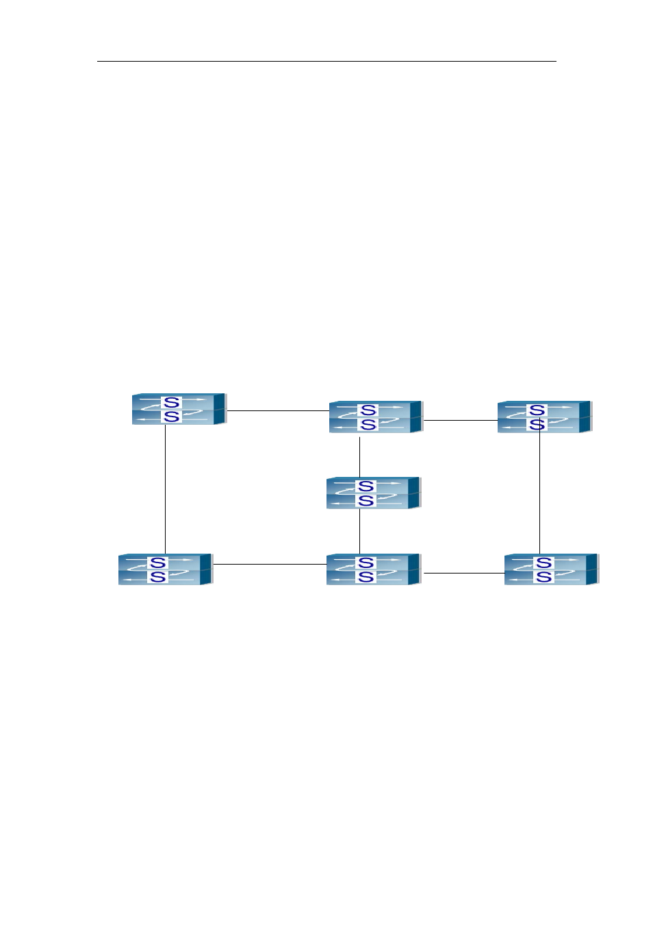
21.4.3 MRPP typical scenario 3
SWITCH A
SWITCH B
SWITCH D
SWITCH C
SWITCH F
SWITCH G
Master
Node
Ring 4000
Ring 100
Master Node
E1
E2
E2
E3
E2
E1
E2
E2
E1
E1
E1
E3
E2
E2
E1
E1
SWITCH E
Fig 21-4 MRPP Scenario 3
In above topology figure, SWITCH B, E, D belongs to two MRPP ring 4000 and 100
separately. SWITCH B and D have one port belonging to two MRPP rings, and SWITCH
E has two ports which belongs to two MRPP rings. Under this configuration, if a switch
port belongs to more than two rings, the type of MRPP ring of the port must be transfer
node.
In the above configuration, SWITCH B, E, D has some port belonging to more than
two rings. The special port changing takes a effect on more than two rings, sometimes
one ring changing can affect another one, so that makes confusion. Thus, you’d better
not configure like this, if not must.
MRPP Ring 4000 configuration Task Sequence: