Parts required for wiring – Yaskawa YASNAC PC NC Maintenance Manual User Manual
Page 129
PC NC Maintenance Manual
The VS-626M5
4-108
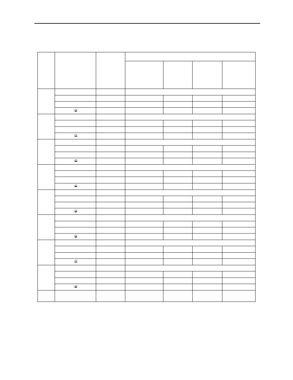
8. Parts Required for Wiring
Notes:
1. Connect using exclusive-use connection bus bar.
2. Wire size is selected assuming external suspended wiring of single 3-core cables at an ambient
temperature of 30
°
(86
°
F).
3. If ambient temperature exceeds 30
°
(86
°
F), allowable current of wire may be lowered.
4. Temperature for each wire indicates maximum allowable conductor temperature.
5. For open chassis type only. Not provided for heat sink externally cooling type.
Table 4.21: 200V Class Converter Power Cable Specifications
Terminal Symbol
Terminal
Screw
Wire Size
UL-approved 75
(167
°
F)
temperature-rated
copper wire
[AWG (mm
2
)]
600V vinyl-
sheath
insulated wire
(IV, VV) 60
(140
°
F) (mm
2
)
600V
crosslinked
polyethylene
wire (IC) 90
(194
°
F) (mm
2
)
600V rubber-
insulated cabtyre
cable (CT) 60
(140
°
F) (mm
2
)
23P7
P/_, N/_
M6
Note 1
R/L1, S/L2, T/L3
M5
14 (2.1)
2
2
2
A1/r, A2/t
M5
14 (2.1)
2
2
2
M4
10 (5.3)
2
2
2
25P5
P/_, N/_
M6
Note 1
R/L1, S/L2, T/L3
M5
12 (3.3)
3.5
2
3.5
A1/r, A2/t
M5
14 (2.1)
2
2
2
M4
10 (5.3)
3.5
2
2
27P5
P/_N, N/_
M6
Note 1
R/L1, S/L2, T/L3
M5
10 (5.3)
3.5
2
3.5
A1/r, A2/t
M5
14 (2.1)
2
2
2
M4
10 (5.3)
3.5
2
3.5
2011
P/_, N/_
M6 ~ 2
(Note 1)
R/L1, S/L2, T/L3
M6
8 (8.4)
8
3.5
8
A1/r, A2/t
M4
14 (2.1)
2
2
2
M6
8 (8.4)
5.5
3.5
5.5
2015
P/_, N/_
M6 ~ 2
(Note 1)
R/L1, S/L2, T/L3
M6
6 (13.3)
14
5.5
14
A1/r, A2/t
M4
14 (2.1)
2
2
2
M6
8 (8.4)
8
5.5
5.5
2018
P/_, N/_
M6 ~ 2
(Note 1)
R/L1, S/L2, T/L3
M6
4 (21.2)
22
8
22
A1/r, A2/t
M4
14 (2.1)
2
2
2
M6
6 (13.3)
8
5.5
8
2022
P/_, N/_
M6 ~ 2
(Note 1)
R/L1, S/L2, T/L3
M6
4 (21.2)
22
14
22
A1/r, A2/t
M4
14 (2.1)
2
2
2
M6
6 (13.3)
14
8
8
2030
P/_, N/_
M6 _~ 2
(Note 1)
R/L1, S/L2, T/L3
M8
2 (33.6)
38
22
38
A1/r, A2/t
M4
14 (2.1)
2
2
2
M8
6 (13.3)
14
8
14
2011 to
2030
A11/r1, A21/t1
(Note 5)
M4
14 (2.1)
2
2
2